Loader Bobcat 773. Manual — part 20

BICS
™
VALVE (S/N 509640660 & Above, S/N
509616542 & Above) (Cont’d)
Lift Arm By–Pass Orifice
Assembly
Install the lift arm by–pass orifice (Item 1) [A] & [B] in the
valve.
Orifice size is 0.078 inch.
Install the fitting (Item 1) [C] on the valve.
A
P–08953
1
C
P–08951
1
–2–26–
773 BICS Loader
Service Manual
B
P–08952
1

BICS
™
VALVE (S/N 509640660 & Above, S/N
509616542 & Above) (Cont’d)
Installation
Install the four large O–rings (Item 1) [A] and the small
O–ring (Item 2) [A] on the top of the control valve.
Install the BICS
™
valve on the control valve [B].
Install the six mounting bolts [C].
The chart below lists the correct torque specifications and
tightening sequence when reinstalling the BICS
™
valve
assembly to the control valve. Thoroughly clean and dry
bolts and threads in valve. Use liquid adhesive LOCTITE
#242 or equivalent.
Step
1
2
3*
Torque
110–130 in.–lbs.
(12,4–14,7 Nm)
190–210 in.–lbs.
(21,5–23,7 Nm)
190–210 in.–lbs.
(21,5–23,7 Nm)
Sequence
1, 2, 3, 4, 5 & 6
*Torque must be 190–210 in.–lbs. (21,5–23,7 Nm) for
every bolt or repeat step 3.
A
P–08950
2
1
1
C
P–08948
5
1
3
4
2
6
773 BICS Loader
–2–27–
Service Manual
B
P–08949
CONTROL VALVE (S/N 509640660 & Above, S/N
509616542 & Above) (Cont’d)
Removal And Installation
Stop the engine. Use the lift lock valve knob to release the
hydraulic pressure. Raise the seat bar.
Raise the operator cab. (See Page 1–1.)
Remove the steering control panel. (See Page 3–1.)
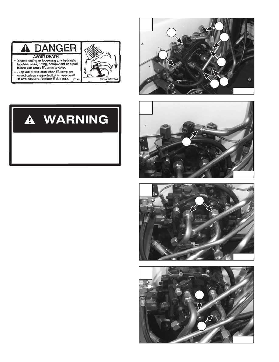
Clean area around the control valve.
Mark all tubelines for correct installation.
Disconnect the wire harness connectors (Item 1) [A] from
the auxiliary solenoid connectors.
Disconnect the wire harness connector (Item 2) [A] from
the BICS
™
valve solenoid connector.
Installation: Install a never modify sta–strap around the
connector (Item 2) [A].
Disconnect the drain hoses (Item 3) [A] from the main
control valve.
Disconnect the hose (Item 4) [A] from the lift arm by–pass
control valve.
Disconnect the outlet tubeline (Item 1) [B] from the
control valve.
Disconnect both tubelines (Item 1) [C] from the auxiliary
section of the control valve.
Disconnect the tilt tubelines (Item 1) [D].
Never work on a machine with the lift arms up
unless the lift arms are secured by an approved
lift arm support device. Failure to use an
approved lift arm support device can allow the
lift arms or attachment to fall and cause injury
or death.
W–2059–0598
Revised Jan. 99
Raise the lift arms and install an approved lift arm support
device. (See Page 1–1.)
A
N–15066
1
3
3
2
3
1
4
C
N–15064
1
D
N–15063
1
1
–2–28–
773 BICS Loader
Service Manual
B
N–15065
1
CONTROL VALVE (S/N 509640660 & Above, S/N
509616542 & Above) (Cont’d)
Removal And Installation (Cont’d)
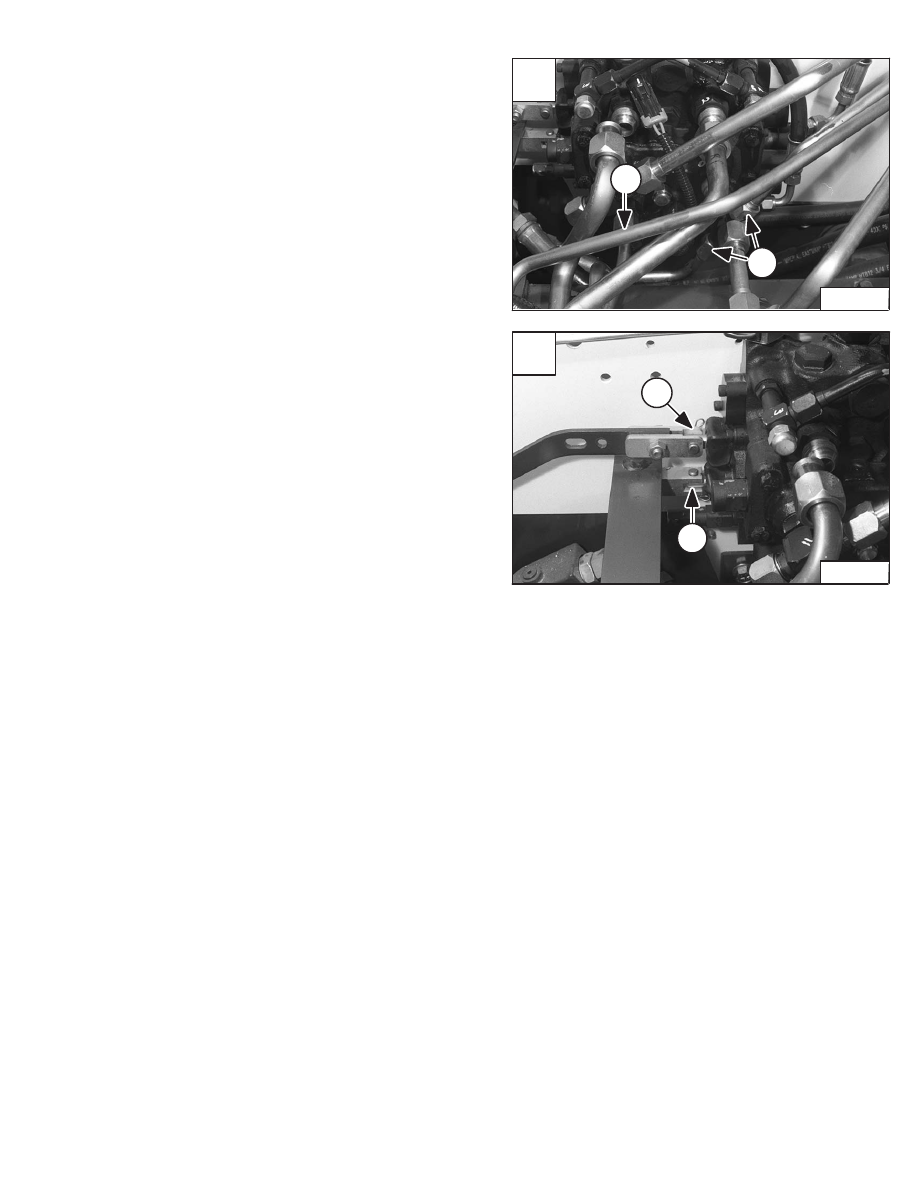
Disconnect the lift tubelines (Item 1) [A].
Remove the clevis pin (Item 1) [B] from the tilt spool
linkage.
Remove the clevis pin (Item 2) [B] from the lift spool
linkage.
NOTE: The lift lock valve has been removed for
clarity purpose only.
A
N–15062
1
1
773 BICS Loader
–2–29–
Service Manual
B
N–15061
1
2
Нет комментариевНе стесняйтесь поделиться с нами вашим ценным мнением.
Текст