Loader Bobcat 773. Manual — part 117

–10–32–
Service Manual
773 BICS Loader
CONTROL HANDLE (ADVANCED HAND CONTROL) (AHC) (W/PUSH BUTTON FLOAT)(Cont’d)
Controller Connector And Wire Identification
Revised June 01
P/N
PIN
DESCRIPTION
C–430
CONNECTOR, METRI–PACK
Orange/White
A
SWITCHED BATTERY POWER
Black
B
GROUND
C–431
MALE, 10–WAY
Brown/Dk. Green
A
SIGNAL FROM LIFT CONTROL
HANDLE INPUT
Purple/Yellow
B
FLOAT SWITCH ON/OFF
Pink/Dk. Green C
SIGNAL FROM TILT CONTROL
HANDLE INPUT
Dk. Blue
D
TILT HIGH REFERENCE TO
RESISTIVE INPUTS
Dk.Blue/White
E
TILT LOW REFERENCE TO
RESISTIVE INPUTS
Dk.Blue/White
F
LIFT LOW REFERENCE TO
RESISTIVE INPUTS
Dk. Blue
G
LIFT HIGH REFERENCE TO
RESISTIVE INPUTS
Purple/White
H
BICS INPUT STATUS
Purple/Red
J
AHC STATUS OUTPUT
K
OPEN
P/N
PIN
DESCRIPTION
C–428
CONNECTOR, 8 WAY PLUG (LIFT) (TOP
ACTUATOR)
Dk.Blue/White
1
LOW REFERENCE TO RESISTIVE INPUTS
Lt. Green/White 2
SIGNAL FROM LIFT ACTUATOR
Dk. Blue
3
HIGH REFERENCE TO RESISTIVE INPUTS
4
OPEN
Brown/White
5
LIFT SPOOL ACTUATOR MOTOR (–)
6
OPEN
7
OPEN
Brown/Yellow
8
LIFT SPOOL ACTUATOR MOTOR (+)
C–429
CONNECTOR, 8 WAY PLUG (TILT) (BOTTOM
ACTUATOR)
Dk. Blue/White
1
LOW REFERENCE TO RESISTIVE INPUTS
Lt. Blue/White
2
SIGNAL FROM TILT ACTUATOR
Dk. Blue
3
HIGH REFERENCE TO RESISTIVE INPUTS
4
OPEN
Pink/White
5
TILT SPOOL ACTUATOR MOTOR (–)
6
OPEN
7
OPEN
Pink/Yellow
8
TILT SPOOL ACTUATOR MOTOR (+)
C–428
C–430
C–429
C–431
CONTROL HANDLE (ADVANCED HAND CONTROL)
(AHC) (W/PUSH BUTTON FLOAT) (Cont’d)
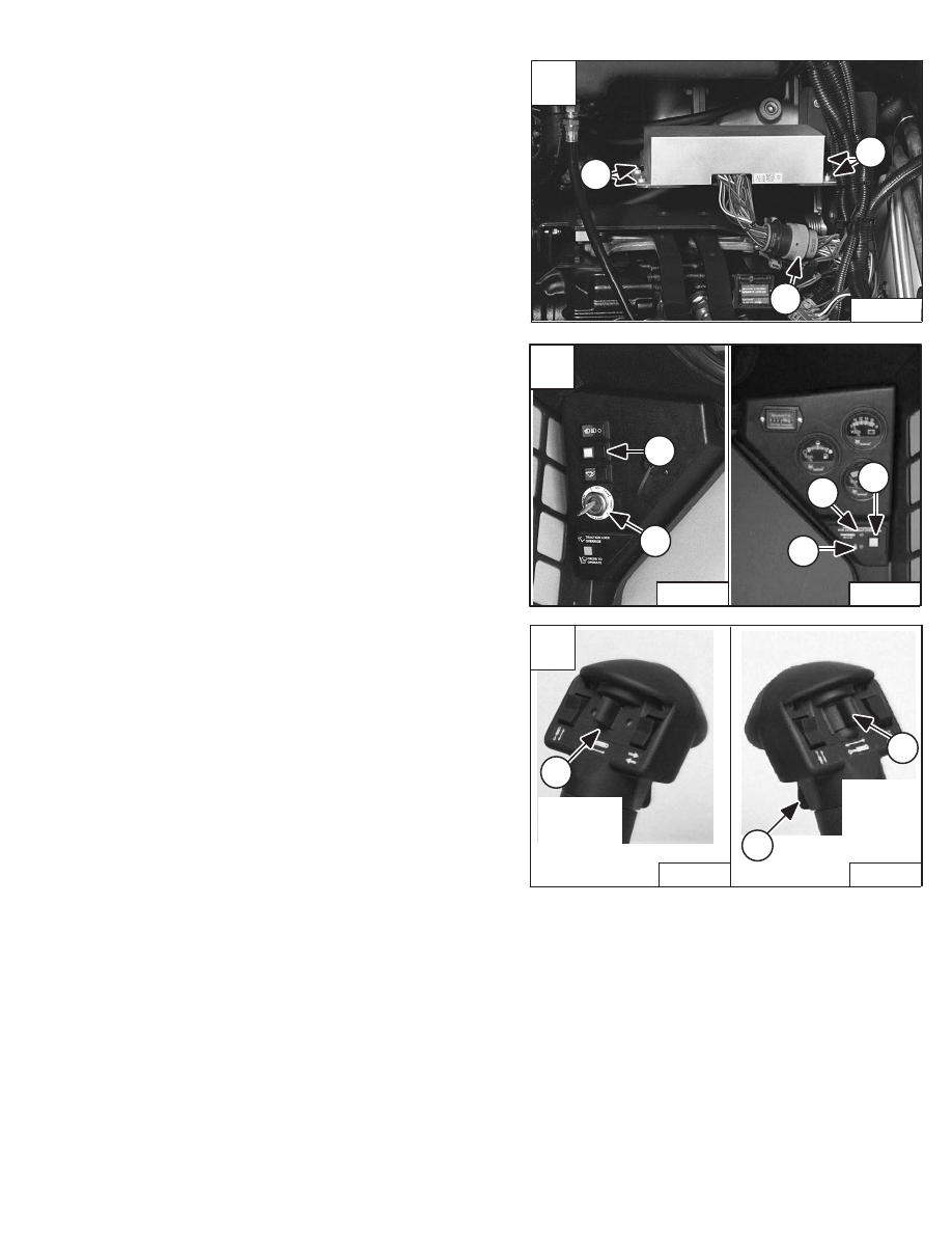
AHC/PWM Controller Removal And Installation
Raise the operator cab. (See Page 1–1.)
Remove the four mounting bolts (Item 1) [A] from the
controller.
Disconnect the wiring harness connectors (Item 2) [A]
from the controller.
Remove the controller from the loader.
Test
•
The wiring harness connectors must be connected to
the controller [A].
•
Take voltage measurements by probing into wires near
the controller shown in figure [A]. All connectors must
remain plugged into their respectful harness.
•
Turn the key to the ON position (Item 1) [B] with the
engine OFF.
•
Turn the switches ON to get their appropriate readings.
(See chart listed below for switch locations.)
•
Press the auxiliary hydraulic switch (Item 2) [B] twice.
Both Green lights will be ON.
•
For individual voltage readings see Page 10–16.
Key Switch
Item 1 [B]
Auxiliary Hydraulic Switch
Item 2 [B]
Momentary Light
Item 3 [B]
Detent Light
Item 4 [B]
High Flow Switch
Item 5 [B]
Proportional Flow Switch
Item 1 [C]
Detent Switch
Item 2 [C]
Rear Aux. Switch (Base & Rod)
Item 3 [C]
A
N–17777
1
1
2
B
P–10466
N–17919
1
2
4
5
3
C
P–13254
Left
Right
Steering
Lever
Steering
Lever
Control
Control
P–13255
3
2
1
Service Manual
–10–33–
773 BICS Loader
Revised Nov. 01
1
C
N–22803
2
1
1
D
N–22790
A
P–16581
1
–10–34–
Service Manual
773 BICS Loader
CONTROL HANDLE
(ADVANCED HAND CONTROL)
(AHC) W/PUSH BUTTON FLOAT (Cont’d)
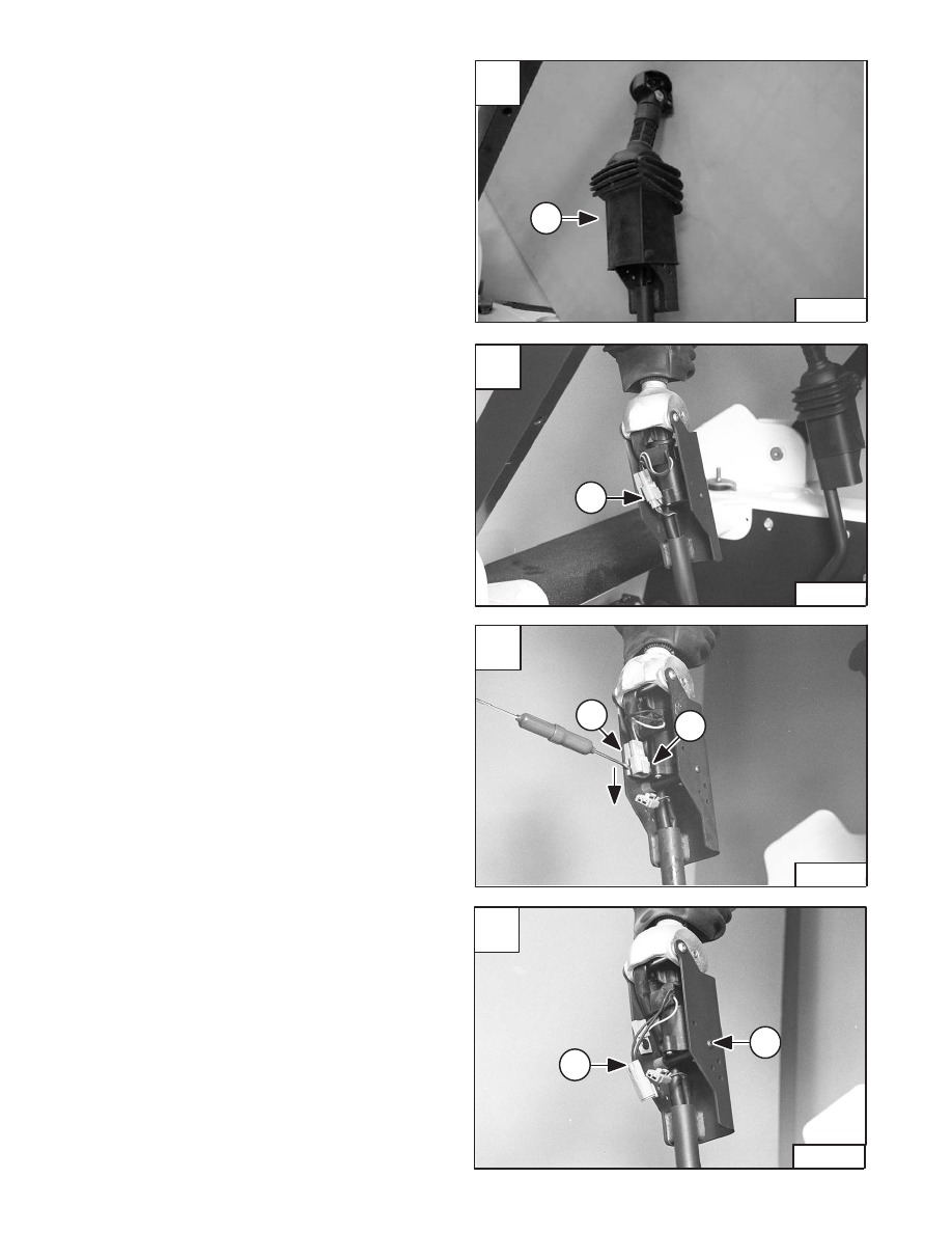
Handle Sensor Removal And Installation
To remove the handle sensor, slide the rubber handle cover
(Item 1) [A] up the handle.
Disconnect the loader control harness (Item 1) [B] from the
handle control harness.
Using a small screwdriver remove the handle control
electrical connector from the clip (Item 1) [C] by pushing
the connector down out of the connector clip (Item 2) [C].
Using an allen wrench, remove one of the two mounting
screws (Item 1) [D] from the handle sensor.
Installation: Tighten the handle sensor mounting screws
to 85 in.–lbs. (9,6 Nm) torque.
Revised June 01
B
N–22797
1
A
N–22793
2
P–16580
1
3
3
3
1
2
C
P–16576
D
N–22799
1
Service Manual
–10–35–
773 BICS Loader
CONTROL HANDLE
(ADVANCED HAND CONTROL)
(AHC) W/PUSH BUTTON FLOAT (Cont’d)
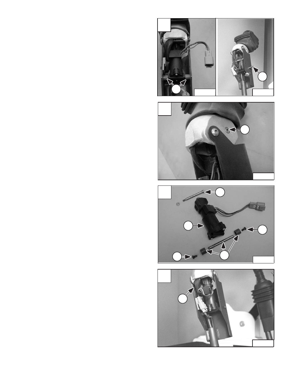
Handle Sensor Removal And Installation (Cont’d)
Remove the two plastic spacers (Item 1) [A] and the metal
spacer (Item 2) [A] from the handle sensor.
Remove the top mounting bolt (Item 1) [B] from the handle
sensor.
Remove the handle sensor (Item 1) [C] from the handle
assembly.
NOTE: The sensor (Item 1) [C] can only be replaced as
a complete assembly.
Check the spacers (Item 2) [C] and screws (Item 3) [C] and
replace as needed.
Installation: When installing the handle sensor into the
control handle, check the routing of the switch handle wire
harness (Item 1) [D] to assure proper return of the control
handle to neutral and minimize harness movement.
Revised June 01
B
P–16574
1
Нет комментариевНе стесняйтесь поделиться с нами вашим ценным мнением.
Текст