Bobcat S150. Manual — part 17

S150 Bobcat Loader
53
Operation & Maintenance Manual
SERVICE SCHEDULE
Chart
Maintenance work must be done at regular intervals. Failure to do so will result in excessive wear and early failures. The
service schedule is a guide for correct maintenance of the Bobcat loader.
WARNING
Instructions are necessary before operating or servicing machine. Read
and understand the Operation & Maintenance Manual, Handbook and signs
(decals) on machine. Follow warnings and instructions in the manuals
when making repairs, adjustments or servicing. Check for correct function
after adjustments, repairs or service. Untrained operators and failure to
follow instructions can cause injury or death.
W-2003-0903
SERVICE SCHEDULE
HOURS
ITEM
SERVICE REQUIRED
8-10
50
100
■
250
■
500
■
1000
Engine Oil
Check the oil level and add as needed.
Engine Air Filter and Air System
Check display panel. Service only when required. Check for leaks and
damaged components.
Engine Cooling System
Clean debris from oil cooler, radiator & grill.
Lift Arms, Cylinders, Bob-Tach
Pivot Pins and Wedges
Lubricate with multi-purpose lithium based grease.
Tires
Check for damaged tires and correct air pressure.
Seat Belt, Seat Bar, Control
Interlocks
Check the condition of seat belt. Check the sear bar and control interlocks for
correct operation. Clean dirt and debris from moving parts.
Bobcat Interlock Control Systems
(BICS™)
Check that four (4) BICS™ indicator lights and functions are activated. See
details in this Manual.
Safety Signs and Safety Treads
Check for damaged signs (decals) and safety treads. Replace any signs or
safety treads that are damaged or worn.
Operator Cab
Check the fastening bolts, washers and nuts. Check the condition of the cab.
Indicators and Lights
Check for correct operation of all indicators and lights.
Fuel Filter
Remove the trapped water.
Heater Filters
Clean or replace filters as needed during heating season.
Hydraulic Fluid, Hoses and
Tubelines
Check fluid level and add as needed. Check for damage and leaks. Repair or
replace as needed.
Final Drive Trans. (Chaincase),
Foot Pedals, Hand Controls or
Steering Levers
Check oil level. Check for correct operation. Repair or adjust as needed.
Wheel Nuts
Check for loose wheel nuts and tighten to 142-156 Nm torque.
❏
Parking Brake
Check operation.
Battery
Check cables, connections and electrolyte level. Add distilled water as needed.
Engine/Hydro. Drive Belt
Check for wear or damage. Check idler arm stop.
*
Alternator Belt
Check tension and adjust as needed.
Air Condition Belt
Check belt for wear. Adjust or replace as needed.
Bobcat Interlock Control System
(BICS™)
Check the function of the lift arm by-pass control.
Fuel Filter
Replace filter element.
Steering Shaft
Grease fittings.
Fan Drive Gearbox
Check gear lube level.
Engine Oil and Filter
Replace oil and filter. Use CD or better grade oil and Bobcat filter.
^
Hydraulic Reservoir Breather Cap Replace the reservoir breather cap.
Hyd./Hydro. Filter
●
Replace the filter element.
Final Drive Trans. (Chaincase)
Replace the fluid.
Hydraulic Reservoir
Replace the fluid.
Case Drain Filters
Replace the filters.
❏
Check wheel nut torque every 8 hours for the first 24 hours.
*
Inspect the new belt after first 50 hours.
●
Also replace hydraulic/hydrostatic filter element when the transmission warning light comes ON.
^ First oil and filter change must occur at 50 hours; 500 hours thereafter.
■
Or every 12 months.

S150 Bobcat Loader
Operation & Maintenance Manual
54
LIFT ARM SUPPORT DEVICE
Maintenance and service work can be done with the lift
arms lowered. If the lift arms are raised, use the following
procedures to engage and disengage an approved lift
arm support device.
Engaging The Lift Arm Support Device
WARNING
Never work on a machine with the lift arms up unless
the lift arms are secured by an approved lift arm
support device. Failure to use an approved lift arm
support device can allow the lift arms or attachment
to fall and cause injury or death.
W-2059-0598
WARNING
Service lift arm support device if damaged or if parts
are missing. Using a damaged lift arm support or
with missing parts can cause lift arms to drop
causing injury or death.
W-2271-1197
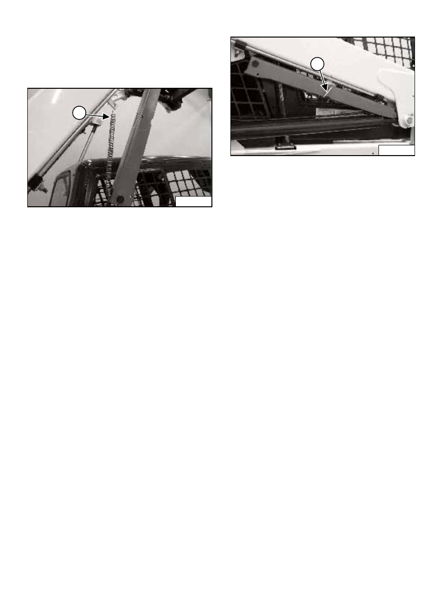
Figure 101
Put jackstands under the rear corners of the loader
frame.
Disconnect the spring (1) [Figure 101] from the lift arm
support device retaining pin. Support the lift arm support
device (2) [Figure 101] with your hand and remove the
retaining pin (3) [Figure 101].
Figure 102
Lower the lift arm support device to the top of the lift
cylinder. Hook the free end of the spring (1) [Figure 102]
to the lift arm support device so there will be no
interference with the support device engagement.
Sit in the operator’s seat, fasten the seat belt and lower
the seat bar. Start the engine.
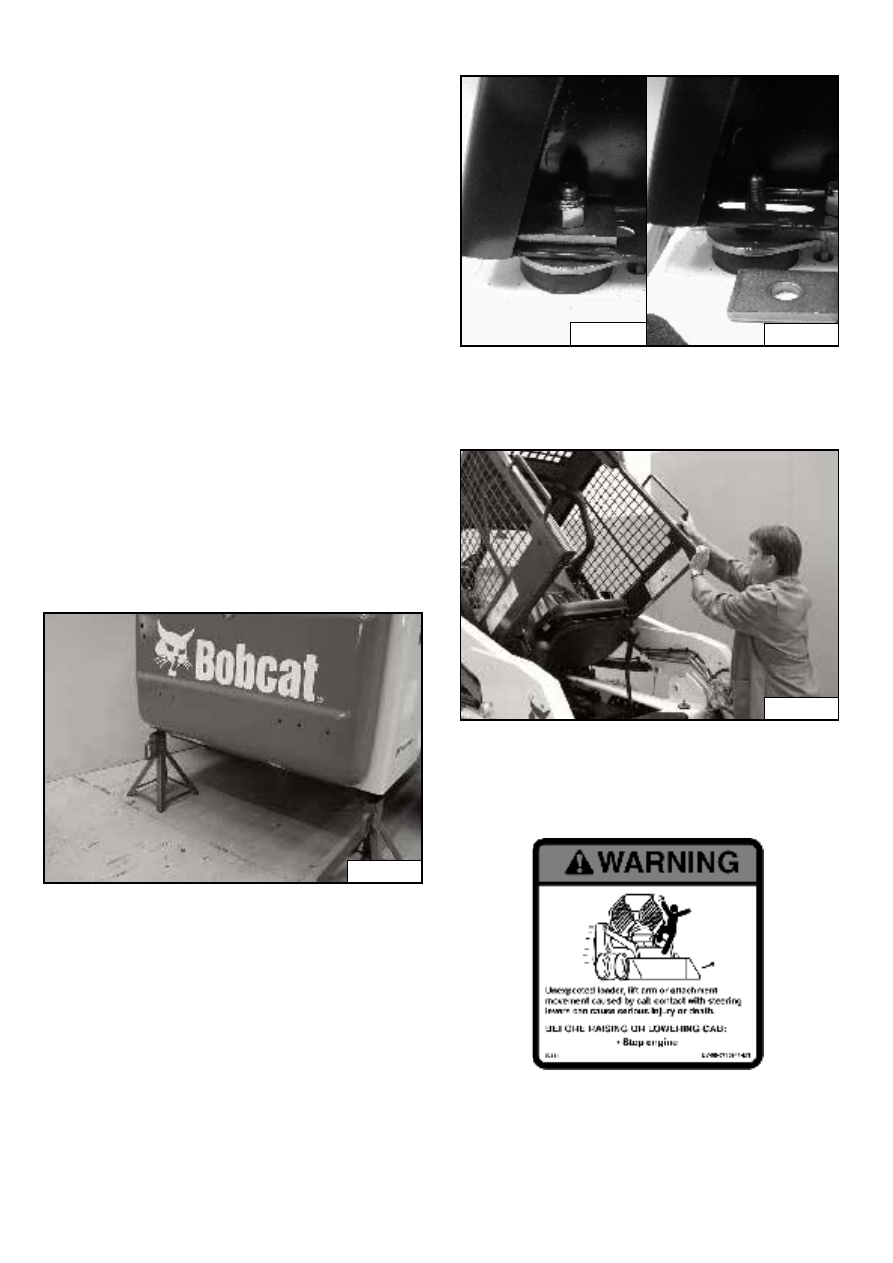
Figure 103
Raise the lift arms until the lift arm support device drops
onto the lift cylinder rod (Inset) [Figure 103].
Lower the lift arms slowly until the support device is held
between the lift arm and the lift cylinder. Stop the engine.
Raise the seat bar and move both pedals until both
pedals lock.
Install pin (1) [Figure 103] into the rear of the lift arm
support device below the cylinder rod.
P-45251
1
3
2
P-45252
1
N-20524
P-10136
1
S150 Bobcat Loader
55
Operation & Maintenance Manual
LIFT ARM SUPPORT DEVICE (CONT’D)
Disengaging The Lift Arm Support Device
Remove the pin from the lift arm support device.
Figure 104
Connect the spring (1) [Figure 104] from the lift arm
support device to the bracket below the lift arms.
Sit in the operator’s seat fasten the seat belt and lower
the seat bar.
Start the engine.
Figure 105
Raise the lift arms a small amount. The spring will lift the
support device off the lift cylinder rod. Lower the lift arms.
Stop the engine.
Raise the seat bar, disconnect the seat belt, move pedals
until both pedals lock and exit the cab.
Disconnect the spring from the bracket.
Raise the support device into storage position and insert
pin (1) [Figure 105] through lift arm support device and
bracket. Connect the spring to the pin.
Remove the jackstands.
P-45486
1
P-45251
1
S150 Bobcat Loader
Operation & Maintenance Manual
56
OPERATOR CAB
The Bobcat loader has an operator cab (ROPS and
FOPS) as standard equipment to protect the operator
from rollover and falling objects. Check with your dealer if
the operator cab has been damaged. The seat belt must
be worn for rollover protection.
ROPS / FOPS - Roll Over protective Structure per
SAE J1040 and ISO 3471, and Falling Object Protective
Structure per SAE J1043 and ISO 3449, Level I. Level II
is available.
Level I - Protection from falling bricks, small concrete
blocks, and hand tools encountered in operations such as
highway maintenance, landscaping, and other
construction sites.
Level II - Protection from falling trees, rocks: for machines
involved in site clearing, overhead demolition or forestry.
Raising The Operator Cab
Always stop the engine before raising or lowering the cab.
Stop the loader on a level surface. Lower the lift arms. If
the lift arms must be up while raising the operator cab,
install the lift arm support device. (See LIFT ARM
SUPPORT DEVICE on Page 54.)
Figure 106
Install jackstands under the rear of the loader frame
[Figure 106].
Figure 107
Remove the nuts and plates [Figure 107] (both sides) at
the front corners of the cab.
Figure 108
Lift on the grab handles and bottom of the operator cab
[Figure 108] slowly until the cab is all the way up and the
latching mechanism engages.
Advanced Control System (ACS) Only
P-43747
P-31289
P-31288
P-45261
Нет комментариевНе стесняйтесь поделиться с нами вашим ценным мнением.
Текст