Bobcat S150. Manual — part 9

S150 Bobcat Loader
19
Operation & Maintenance Manual
HYDRAULIC CONTROLS (CONT’D)
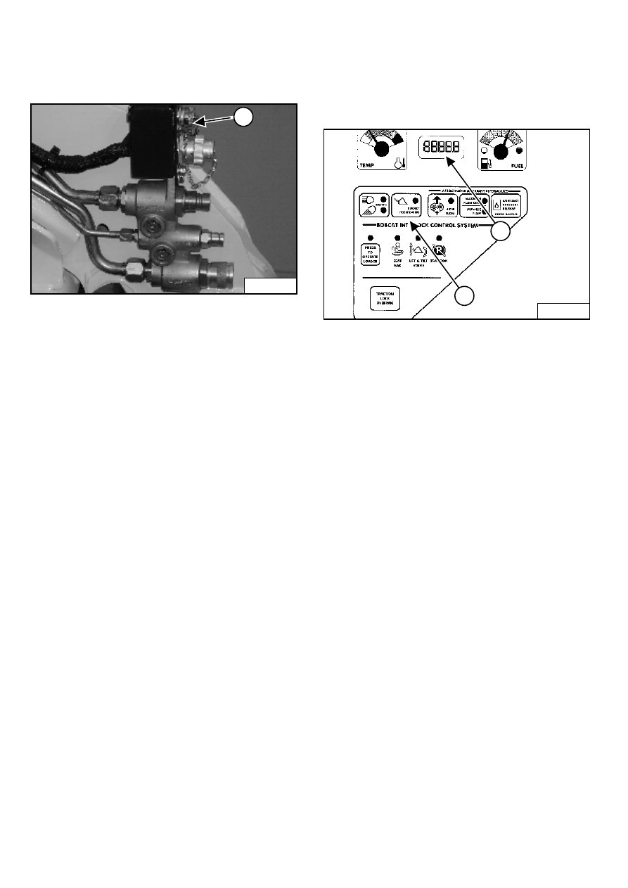
FRONT Auxiliary Hydraulics Operation - VARIABLE
FLOW
Figure 39
Press the auxiliary hydraulics button for VARIABLE
FLOW (See also Auxiliary Hydraulics Button - VARIABLE
FLOW on Page 18).
Push the switch (1) [Figure 39] to the right or left to
change the fluid flow direction of the front quick couplers.
(EXAMPLE: Open and close grapple teeth.)
FRONT Auxiliary Hydraulics Operation - MAXIMUM
FLOW
Press the auxiliary hydraulics button for MAXIMUM
FLOW.
Push the switch (1) [Figure 39] to the right or left to
change the fluid flow direction of the front quick couplers.
(EXAMPLE: Open and close grapple teeth.)
FRONT Auxiliary Hydraulics Operation -
CONTINUOUS FLOW
After selecting VARIABLE or MAXIMUM FLOW, press
the front switch (2) [Figure 39] to give the front quick
couplers a constant flow of fluid with the female coupler
being pressurized. (EXAMPLE: Operate a backhoe.)
REVERSE CONTINUOUS FLOW - To set reverse flow
(male coupler pressurized), select VARIABLE or
MAXIMUM FLOW, then, while holding the auxiliary
switch (1) [Figure 39] to the left, press the front
switch (2) [Figure 39]. Reverse flow can be used only
with augers, power rakes, sweepers, tillers, and vibratory
rollers.
To release from continuous operation, press the front
switch (2) [Figure 39] a second time.
REAR Auxiliary Hydraulics Operation (If Equipped)
Figure 40
The switches on the left hand lever control the rear
auxiliary hydraulics.
Press the auxiliary hydraulics button for MAXIMUM
FLOW (See also Auxiliary Hydraulics Button - MAXIMUM
FLOW ONLY on Page 18).
Push the switch (3) [Figure 39] to the right or left to
change the fluid flow direction to rear quick couplers
[Figure 40]. (EXAMPLE: Raise and lower rear
stabilizers.)
WARNING
Diesel fuel or hydraulic fluid under pressure can
penetrate skin or eyes, causing serious injury or
death. Fluid leaks under pressure may not be visible.
Use a piece of cardboard or wood to find leaks. Do
not use your bare hand. Wear safety goggles. If fluid
enters skin or eyes, get immediate medical attention
from a physician familiar with this injury.
W-2007-0497
P-31833
2
1
3
P-16537
P-48004
S150 Bobcat Loader
Operation & Maintenance Manual
20
HYDRAULIC CONTROLS (CONT’D)
Attachment Control Device (ACD) (If Equipped)
Figure 41
You will need the Dual-Connector (7-pin/14-pin) kit (1)
[Figure 41] to operate early model attachments. See
your Bobcat loader dealer.
Bucket Position Valve Operation (If Equipped)
The function of the bucket position valve is to keep the
bucket in the same approximate position it is in before
you begin raising the lift arms.
Figure 42
Press BUCKET POSITIONING button (1) [Figure 42] to
engage the bucket position function. (The light will be on.)
Press again to disengage.
Bucket Positioning functions only during upward lift cycle.
SHUTDOWN FEATURE
Press and hold the BUCKET POSITIONING button (1)
[Figure 42] for 2 seconds. Shtdn will appear in the
HOURMETER / CODE DISPLAY (2) [Figure 42]
(Operational Code will also appear.)
P-31832
1
B-15551
1
2
S150 Bobcat Loader
21
Operation & Maintenance Manual
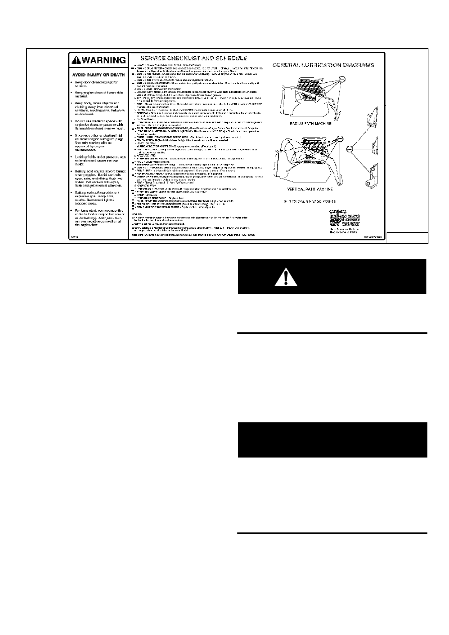
DAILY INSPECTION
Maintenance work must be done at regular intervals.
Failure to do so will result in excessive wear and early
failures. The Service Schedule (above) is a guide for
correct maintenance of the Bobcat Loader. It is located
inside the rear door of the loader.
Daily Inspection and Maintenance
•
Engine Oil Level
•
Hydraulic/Hydrostatic Fluid Level
•
Engine Air Filter, Check System for Damage or Leaks
•
Engine Coolant System, Check System for Damage
or Leaks
•
Operator Cab and Cab Mounting Hardware
•
Seat Belt
•
Seat Bar and Control Interlocks
•
Grease Pivot Pins (Lift Arms, Bob-Tach™, Cylinders,
Bob-Tach Wedges)
•
Tires, Check for Wear, Damage, Correct Air Pressure
•
Fuel Filter, Remove Trapped Water
•
Loose or Broken Parts, Repair or Replace as
Necessary
•
Lift Arm Support Device. Replace if Damaged
•
Bobcat Interlock Control System (BICS™)
WARNING
Operator must have instructions before running the
machine. Untrained operators can cause injury or
death.
W-2001-0596
NOTE: Fluids such as engine oil, hydraulic fluid,
coolant, etc. must be disposed of in an
environmentally safe manner. Some
regulations require that certain spills and
leaks on the ground must be cleaned in a
specific manner. See local, state and federal
regulations for correct disposal.
IMPORTANT
PRESSURE WASHING DECALS
•
Never direct the stream at a low angle toward the
decal that could damage the decal causing it to
peel from the surface.
•
Direct the stream at a 90 degree angle and at
least 300 mm from the decal. Wash from the
center of the decal toward the edges.
I-2225-0204
6734534

S150 Bobcat Loader
Operation & Maintenance Manual
22
PRE-STARTING PROCEDURES
Before Starting The Engine
Figure 43
Use the bucket or attachment steps, grab handles and
safety treads (on the loader lift arms and frame) to get on
and off the loader [Figure 43]. Do not jump.
Safety treads are installed on the Bobcat Loader to
provide a slip resistant surface for getting on and off the
loader.
Keep safety treads clean and replace when damaged.
Replacement treads are available from your Bobcat
dealer.
Read and understand the Operation & Maintenance
Manual and the Operator’s Handbook (1) [Figure 43]
before operating the loader.
The Operation & Maintenance Manual and other manuals
can be kept in a container (2) [Figure 43] provided
behind the operator seat.
WARNING
Instructions are necessary before operating or
servicing machine. Read and understand the
Operation & Maintenance Manual, Operator’s
Handbook and signs (decals) on machine. Follow
warnings and instructions in the manuals when
making repairs, adjustments or servicing. Check for
correct function after adjustments, repairs or service.
Untrained operators and failure to follow instructions
can cause injury or death.
W-2003-0903
Figure 44
Release the seat lever (1) [Figure 44] and adjust the seat
position for comfortable operation of the loader controls.
Figure 45
Suspension Seat - (Option) Release the lever (1)
[Figure 45] to adjust the seat distance from the levers
and footrests.
Release the lever (2) [Figure 45] to adjust the angle of
the seat back.
Turn the lever (3) [Figure 45] to adjust the seat cushion
for weight of the operator.
N-20299
2
1
N-18529
2
N-20299
1
P13907
1
P-16052
1
2
3
Нет комментариевНе стесняйтесь поделиться с нами вашим ценным мнением.
Текст