Bobcat S150. Manual — part 8
S150 Bobcat Loader
15
Operation & Maintenance Manual
HYDRAULIC CONTROLS
Standard Operation (Foot Pedal)
Two foot pedals (or optional hand controls) control the
hydraulic cylinders for the lift and tilt functions.
Put your feet on the pedals (or footrests) and KEEP
THEM THERE any time you operate the loader.
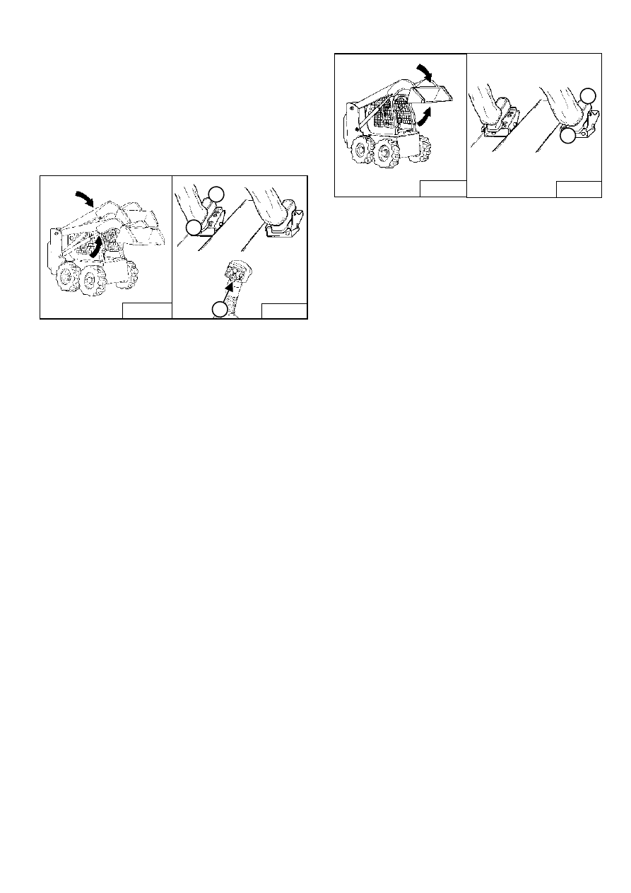
Figure 28
Standard Controls (Also ACS in Foot Pedal Mode)
Lift Arm Operation - (Left Pedal)
Push the heel (1) [Figure 28] of the pedal to raise the
lift arms.
Push the toe (2) [Figure 28] of the pedal to lower the
lift arms.
Lift Arm Float Position - (Left Pedal)
Push the toe (2) [Figure 28] of the pedal all the way
forward until it locks into the float position.
Use the float position of the lift arms to level loose
material while driving backward.
Raise the lift arms to disengage the float position.
Lift Arm Float Position (With ACS) - (Left Pedal)
Press and hold the Float button (3) [Figure 28].
Push the toe (2) [Figure 28] of the pedal forward to
lower the lift arms. Then release the float button.
Use the float position of the lift arms to level loose
material while driving backward.
Raise the lift arms to disengage the float position.
Figure 29
Tilt Operation - (Right Pedal)
Push the heel (1) [Figure 29] of the pedal to tilt the
bucket backwrd.
Push the toe (2) [Figure 29] of the pedal to tilt the
bucket forward.
B-15579
3
B-15781
1
2
B-15581A
B-15973
1
2

S150 Bobcat Loader
Operation & Maintenance Manual
16
HYDRAULIC CONTROLS (CONT’D)
Advanced Control System (ACS) in HAND Control
Mode
Figure 30
Lift Arm Operation - (Left Hand Lever)
Move the lever outward (1) [Figure 30] to raise the lift
arms.
Move the lever inward (2) [Figure 30] to lower the lift
arms.
Lift Arm Float Position - (Left Hand Lever)
Press and hold the Float Button (3) [Figure 30] while
the lever is in neutral. Move the lever to lift arm down
position (2) [Figure 30], then release the button.
Press Float Button again or move the lever to lift arm
up position (3) [Figure 30].
Use the float position of the lift arms to level loose
material while driving backward.
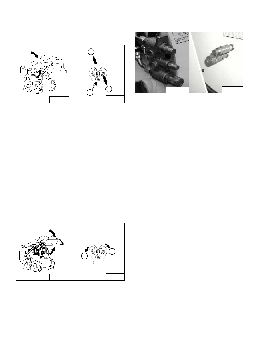
Figure 31
Tilt Operation - (Right Hand Lever)
Move the lever inward (1) [Figure 31] to tilt the bucket
backward.
Move the lever outward (2) [Figure 31] to tilt the
bucket forward.
Selectable Joystick Control (SJC) - ‘H’ Control
Pattern
Figure 32
Lift Arm Operation - (Left Hand Joystick)
Move the joystick outward (1) [Figure 32] to raise the
lift arms.
Move the joystick inward (2) [Figure 32] to lower the
lift arms.
Lift Arm Float Position - (Left & Right Hand Joysticks)
Press and hold the Float Button (3) [Figure 32] while
the joysticks are in neutral. Move the left joystick to lift
arm down position (2) [Figure 32], then release the
button.
Use the float position of the lift arms to level loose
material while driving backward.
Press Float Button again or move the left joystick to lift
arm up position (3) [Figure 32] to disengage.
Figure 33
Tilt Operation - (Right Hand Joystick)
Move the joystick inward (1) [Figure 33] to tilt the
bucket backward.
Move the joystick outward (2) [Figure 33] to tilt the
bucket forward.
B-15579
B-15781
1
2
3
B-15581A
B-15781
2
1
B-15579
B-19873
B-19874
1
2
3
Right
Joystick
Left
Joystick
B-15581A
B-19873
B-19874
2
1
Left
Joystick
Right
Joystick
S150 Bobcat Loader
17
Operation & Maintenance Manual
HYDRAULIC CONTROLS (CONT’D)
Selectable Joystick Control (SJC) - ‘ISO’ Control
Pattern
Figure 34
Lift Arm Operation - (Right Hand Joystick)
Move the joystick backward (1) [Figure 34] to raise
the lift arms.
Move the joystick forward (2) [Figure 34] to lower the
lift arms.
Lift Arm Float Position - (Right Hand Joystick)
Press and hold the Float Button (3) [Figure 34] while
the joystick is in neutral. Move the joystick to lift arm
down position (2) [Figure 34], then release the
button.
Use the float position of the lift arms to level loose
material while driving backward.
Press Float Button again or move the joystick to lift
arm up position (2) [Figure 34] to disengage.
Figure 35
Tilt Operation - (Right Hand Joystick)
Move the joystick inward (1) [Figure 35] to tilt the
bucket backward.
Move the joystick outward (2) [Figure 35] to tilt the
bucket forward.
Quick Couplers
Figure 36
To Connect: Remove dirt or debris from the surface of
both the male and female couplers, and from the outside
diameter of the male coupler. Visually check the couplers
for corroding, cracking, damage or excessive wear. If any
of these conditions exist, the coupler(s) [Figure 36] must
be replaced.
Install the male coupler into the female coupler. Full
connection is made when the ball release sleeve slides
forward on the female coupler.
To Disconnect: Hold the male coupler. Retract the sleeve
on the female coupler until the couplers disconnect.
B-15579
B-15781
3
2
1
Right Joystick
B-15581A
B-15781
2
1
Right Joystick
P-48004
P-31837
S150 Bobcat Loader
Operation & Maintenance Manual
18
HYDRAULIC CONTROLS (CONT’D)
Releasing Hydraulic Pressure (Loader and
Attachment)
WARNING
AVOID BURNS
Hydraulic fluid, tubes, fittings and quick couplers can
get hot when running machine and attachments. Be
careful when connecting and disconnecting quick
couplers.
W-2220-0396
Front Auxiliary Hydraulics
When Connecting: Push the quick couplers tightly
together and hold for five seconds; the pressure is
automatically released as the couplers are installed.
When Disconnecting: Push the quick couplers tightly
together and hold for five seconds; then retract the sleeve
until the couplers disconnect.
Rear Auxiliary Hydraulics
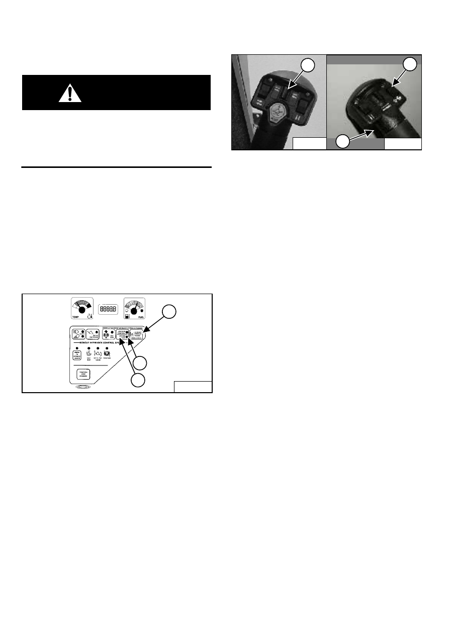
Figure 37
Press and hold the Auxiliary Pressure Release Button (1)
[Figure 37] for 5 seconds.
Auxiliary Hydraulics Button - VARIABLE FLOW
Figure 38
VARIABLE FLOW allows for slow-to-fast movement of
auxiliary functions. If you move the auxiliary switch (1)
[Figure 38] half-way, the auxiliary functions move at
approximately one-half speed.
Press the auxiliary hydraulics button (2) [Figure 37]
once.
The light (3) [Figure 37] will be ON.
Auxiliary Hydraulics Button - MAXIMUM FLOW ONLY
MAXIMUM FLOW ONLY allows for fast movement only. If
you move the auxiliary switch (1 or 3) [Figure 38], the
auxiliary functions move at fast speed; release the switch
to stop auxiliary functions.
Press the auxiliary hydraulics button (1) [Figure 37] a
second time.
The light (3) [Figure 37] will be ON.
Auxiliary Hydraulics Button - DISENGAGE
To disengage, press the auxiliary hydraulics button (1)
[Figure 37] a third time.
Both lights (2 & 3) [Figure 37] will be OFF.
NOTE: When the operator is seated and raises the
seat bar, the Auxiliary Hydraulic System
(Front and Rear) will deactivate.
B-15551
1
2
3
P-31833
2
1
3
P-16537
Нет комментариевНе стесняйтесь поделиться с нами вашим ценным мнением.
Текст