DAF 95XF. Manual — part 343
5
MODIFICATIONS TO THE ELECTRICAL INSTALLATION
Modifications to the electrical installation from chassis number 0E473500
3-58
ALARM SYSTEM SOCKET (A040)
Pin 1
is connected directly to the supply
voltage in front of the contact through
wire 1114 and fuse E108 (wire 1000).
Pin 2
is connected to the direction indicator,
front left (C014), side direction
indicator, left (C016), direction indicator,
rear left (C018) and the electronic unit
CTE-3 (D884) through wire 2006.
Pin 3
is connected to the direction indicator,
front right (C015), side direction
indicator, right (C017), direction
indicator, rear right (C019) and the
electronic unit CTE-3 (D884) through
wire 2007.
Pin 4
is connected directly to the control
switch for interior stepwell lighting, door
switch on driver’s side (E514), the
stepwell lighting on driver’s side
(C062), the electronic unit CTE-3
(D884) and the lighting buzzer relay
(G235) through wire 2600.
Pin 5
is connected directly to the stepwell
lighting on co-driver’s side (C063), the
interior lighting switch on co-driver’s
side (C686), the control switch for
interior stepwell lighting, door switch on
co-driver’s side (E515) through wire
2609, and the interior-lighting diode
prevent feedback to the co-driver’s
stepwell (D708).
Pin 6
is connected directly to the cab-lock
control switch (F009) through wire 3412
and by means of a cab lock connection
(cab without air suspension) (G719) to
the electronic unit CWS (D582) through
wire 3492.
Pin 7
is connected directly to the generator of
integrated voltage regulator (A502)
(D+) and to lighting relay D+ (G107)
through wire 1020. At the same time
pin 7 is connected directly to the
lighting buzzer (B242) and to the
electronic unit CWS (D582).
Pin 9
is connected to the electronic unit of
the central door locking (D862).
Pin 12
is connected to earth.
11
ǹ 0209
5
Modifications to the electrical installation from chassis number 0E473500
MODIFICATIONS TO THE ELECTRICAL INSTALLATION
3-59
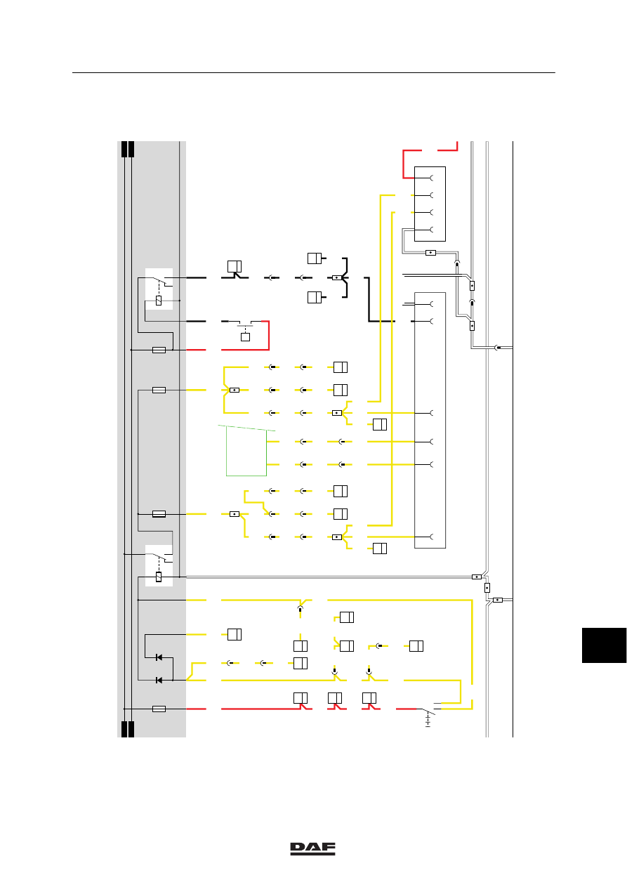
SUPERSTRUCTURE SIDE-LIGHTS
CONNECTOR (A026)
Pin 1
is connected directly to the
(semi-)trailer socket (A000) pin 2
through wire 2102, and to the rear-light/
side light relay (G000) through fuse
E000.
Pin 2
is connected directly to the
(semi-)trailer socket (A000) pin 6
through wire 2103, and to the rear-light/
side light relay (G000) through fuse
E001.
Pin 3
is connected directly to pin 5 of the rear
fog light socket (A001) through wire
1113 and to the supply voltage through
fuse E048.
Pin 4
is connected directly to earth.
CONNECTOR SOCKET FOR REMOTE
CONTROL CONNECTION UPEC (A046)
Pin 1
is connected to point 87 of relay for
ECS power supply (G126) through wire
1297 and fuse E194.
Pin 2
is connected directly to pin 21 of the
UPEC electronic unit (D814) through
wire 3039.
Pin 3
is connected directly to point 5 of relay
for UPEC remote control (G321)
through wire 4100.
Pin 4
is connected directly to pin 8 of switch
for the windscreen wipe/wash
intermittent wipe/E-gas/UPEC vehicle
speed/engine speed (C776) and to pin
34 of the UPEC electronic unit (D814)
through wire 4691.
Pin 5
is connected directly to pin 9 of the
switch for windscreen wipe/wash
intermittent wipe/E-gas/UPEC vehicle
speed/engine speed (C776) and to pin
32 of the UPEC electronic unit (D814)
through wire 4692.
Pin 6
is connected directly to pin 7 of the
switch for windscreen wipe/wash
intermittent wipe/E-gas/UPEC vehicle
speed/engine speed (C776) and to pin
33 of the UPEC electronic unit (D814)
through wire 4693.
Pin 7
is connected to point 86 of the UPEC
engine stop relay (G328).
Pin 8
is connected directly to earth.
11
ǹ 0209

5
MODIFICATIONS TO THE ELECTRICAL INSTALLATION
Modifications to the electrical installation from chassis number 0E473500
3-60
1316630/13-23
EL000309
43
1
23456789
1
0
1
1
1
2
1
3
1
4
1
5
1
6
1
7
1
8
1
9
2
0
2
1
2
2
2
3
2
4
2
5
2
6
2
7
2
8
2
9
3
0
3
1
3
2
3
3
3
4
3
5
3
6
3
7
3
8
3
9
4
0
4
1
4
2
4
3
4
4
4
5
4
6
4
7
4
8
4
9
5
0
5
1
5
2
5
3
1240
1240
1240
1240
1240
1240
1240
1240
1240
1000
1000
1010
1000
1000
1000
1000
1000
1000
1000
1000
1175
1000
1175
1000
1119
1119
1000
1010
1288
1288
1288
3428
1000
3428
1181
1181
1181
1181
1181
1181
1181
1181
1181
1181
1181
3428
25/400
1
187
7
185
1
286
1
288
B042
1
22
21
185
A
114
2/233
1/233
G525
G525
G014
1
3
B
114
2
180
1
180
30
87
G015
E168
40A
A2
A1
A
115
E043
25A
A2
A1
B032
1
21
B033
1
21
C
115
27
321
12/401
1
377
1
321
2
321
D853
7
7
35/402
1
196
2
380
D862
10
36
21
380
B199 308
36
1
276
B200 308
36
B030
1
22
A500
50
B010
M
31
30
G
3
D
B+
D+
A502
7
377
D878
E091
15A
1000
1010
1010
1000
E172
10A
E182
15A
A043
12
A038
12
A004
1
2
5
3
4
A042
12
11
ǹ 0209
5
Modifications to the electrical installation from chassis number 0E473500
MODIFICATIONS TO THE ELECTRICAL INSTALLATION
3-61
1316630/13-23
EL000310
43
54
55
56
57
58
59
60
61
62
63
64
65
66
67
68
69
70
71
72
73
74
75
76
77
78
79
80
81
82
83
84
85
86
87
88
89
90
91
92
93
94
96
96
97
98
99
100
101
102
103
104
105
106
4601
4601
1101
1101
2154
1101
1101
2110
2110
2110
2110
2110
2110
2110
2110
2110
2110
2100
2100
2100
2100
2102
2102
2102
2102
2102
2102
2102
2102
2103
2103
2103
2103
2103
2103
2103
2103
2103
2103
2102
4601
4601
4601
2102
2102
1209
4602
2103
2103
2102
2103
4601
2102
2008
2008
2008
2009
2009
2009
2102
2103
1113
4601
4601
14/403
28/401
22/401
5/401
C775
7
10
2/231
1/231
4/231
D853 B15
7
D852 B10
6
24/401
B130
3
33
4
286
4
288
C775
4
10
5
176
4
281
C773
5
11
C764
5
33
B129
3
33
3
284
C727
2
11
4
176
28/400
7
115
3
281
C012
5
8
2
284
5
495
C074
2
2
4
189
C010
1
8
1
161
8
115
C075
2
8
5
189
C011
2
8
2
161
3
286
C013
2
8
3
288
C021
3
14
22
115
C020
3
14
8/402
D759
1
14
33/400
7/402
6/402
12
495
D
115
E511
1
2
P
C622
0II
I
6
495
9
495
5
115
2
495
6
115
4
495
11
495
A000
2
4
1
6
3
5
A026
4
2
3
1
D884
2/
232
30/
232
D878
1010
1000
1010
1000
2100
E084
10A
E000
10A
D609
D610
2154
30
86
85
87A
8
7
G000
2101
E001
10A
M
MM
30
86
85
87A
8
7
G036
4602
E013
10A
1209
11
ǹ 0209
Нет комментариевНе стесняйтесь поделиться с нами вашим ценным мнением.
Текст