DAF 95XF. Manual — part 342
5
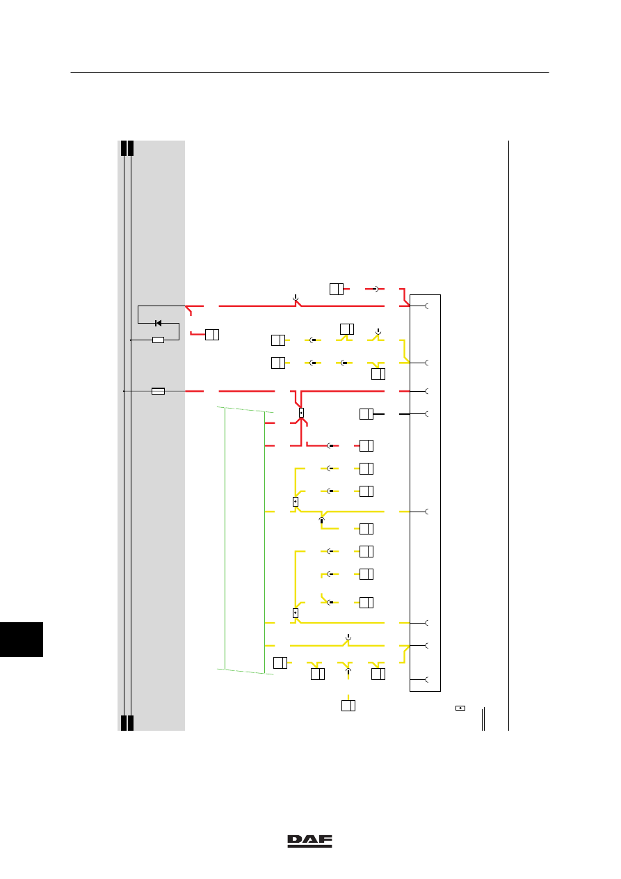
MODIFICATIONS TO THE ELECTRICAL INSTALLATION
Modifications to the electrical installation from chassis number 0E473500
3-54
42
1316630/13-23
EL000307
160
161
162
163
164
165
166
167
168
169
170
171
172
173
174
175
176
177
178
179
180
181
182
183
184
185
186
187
188
189
190
191
192
193
194
195
196
197
198
199
200
201
202
2
03
204
205
206
207
208
209
210
211
212
2600
2600
2600
2006
2006
1114
1114
1114
1114
2609
2609
2609
2609
1020
1020
1020
2600
2600
2600
2006
2006
2006
2007
2006
2006
2007
2007
2007
2007
2007
1114
2007
5063
1114
2609
2609
2609
2609
2600
2006
1114
1020
1020
8
383
D862
3
36
D862
4
36
32/402
D708
1
17
C063
1
17
13/402
D853
B6
7
A502
D+
1
1
114
9
281
C062
1
17
D853
5
7
E514
1
16
C014
1
4
C016
1
4
C017
1
4
2
281
1
185
C018
1
4
3
115
C019
1
4
4
115
C015
1
4
2
286
C765
6
4
4
380
D862
5
36
10
483
8
189
8
190
9
286
E515
2
17
9
383
D878
1010
1000
1010
1000
E108
15A
D668
1020
B036
1024
12
7
42
15
A040
3
9
D884
4/
232
17/
232
1/
232
31/
232
29/
232
9
281
11
ǹ 0209
5
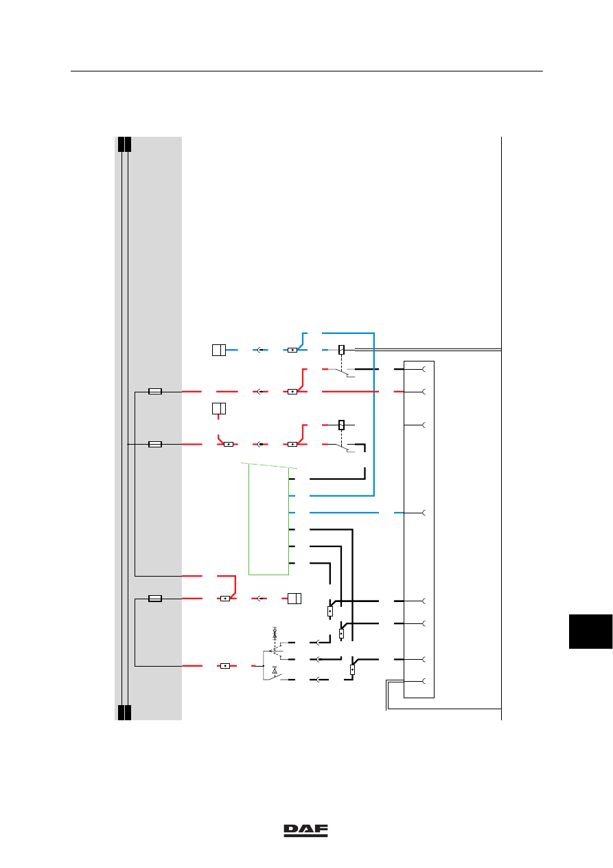
Modifications to the electrical installation from chassis number 0E473500
MODIFICATIONS TO THE ELECTRICAL INSTALLATION
3-55
42
1316630/13-23
EL000308
213
214
215
216
217
218
219
220
221
222
223
224
225
226
227
228
229
230
231
232
233
234
235
236
237
238
239
240
241
242
243
244
245
246
247
248
249
250
251
252
253
254
2
55
2
56
257
258
2
59
260
2
61
262
263
264
265
4099
3039
3402
3039
9029
1247
1247
4693
4691
4692
1248
1248
1247
1247
4693
4693
4693
4691
4692
4691
4692
4692
4692
4099
4691
4691
4693
1297
1297
1297
1297
1234
1234
3402
1297
1234
1234
1234
3402
1234
3402
3402
4100
1297
13/403
11/403
27/402
D878
1010
1000
1010
1000
E143
15A
E194
5A
E184
5A
1248
1247
G126
87
47
4
398
2
398
3
398
C776
6
79
8
18/
295
21/
295
22/
295
D814
32/
295
34/
295
15/
295
33/
295
F000
2
8
B501
A3
2
4
297
8
297
25/402
2
297
3
297
23/400
G328
1
3
52
4
G321
1
3
42
5
A046
2/534
8/534
5/534
4/534
6/534
3/534
1/534
7/534
11
ǹ 0209
5
MODIFICATIONS TO THE ELECTRICAL INSTALLATION
Modifications to the electrical installation from chassis number 0E473500
3-56
43. CONNECTOR SOCKETS FA
DIAGNOSTIC CONNECTOR (A021)
The diagnostic connector is installed on the top
left-hand side in the central cabinet. This is the
connector to which DAVIE is connected. After
the contact has been activated, the supply
voltage for DAVIE is applied to pin 1 through
fuse E053. Pin 2 is connected to earth. The
remaining pins are meant for the communication
with various systems and are connected to
those systems.
Pin no.
Wire no.
Colour
Description
1
1229
Red
Supply for DAVIE
2
9107
White
Earth
3
3425
Blue
ABS/ASC-D
4
4788
Black
ASL-G
5
4697
Black
ECAS remote control / E-gas 3 / ASL-V /
UPEC
6
7
4732
Black
ECAS 2
8
3064
Blue
Connector 378, pin 5
9
4047
Black
CTE-3
10
3065
Blue
Connector 378, pin 4
11
4883
Black
ZF intarder
12
13
3470
Blue
AGS
14
3037
Blue
D1LC / D3LC Compact auxiliary heating/
Hydronic 10
24V CONNECTOR (A043)
Pin 1
of the 24V connector (A034) is
connected directly to the supply
voltage through wire 1240 and
fuse E091 (behind the contact).
Pin 2
is connected to earth.
ABS CONNECTOR (A004)
Pin 1
of the ABS connector (A004) is
connected directly to the supply
voltage through wire 1119 and
fuse E043.
Pin 2
is connected directly to the
supply voltage through fuse
E172 behind the contact. This
voltage also serves to feed the
ABS unit.
Pins 3 + 4
are both connected to earth.
Pin 5
is connected to the CWS-2 unit
(D583) through wire 3428.
11
ǹ 0209
5
Modifications to the electrical installation from chassis number 0E473500
MODIFICATIONS TO THE ELECTRICAL INSTALLATION
3-57
FA TRAILER CONNECTOR (A000)
Pin 1
of the FA trailer connector (A000) is
connected to earth.
If a connection is made between
contacts 2 and 1 (rear/side marker and
parking lights position) with the lighting
switch (C622), a voltage is applied to
contact 85 of relay G000 through fuse
E084, wire 1101, switch C622 and wire
2100. The relay is activated and a
voltage is applied from wire 1000,
contacts 30 and 87 (from relay G000)
through fuses E000 and E001 to pins 2
(through wire 2102) and 6 (through wire
2103) respectively.
Pin 2
switches the left rear light and pin 6
switches the right rear light.
Pin 3
is connected to the CTE-3 unit (left
direction) through wire 2008.
Pin 4
is connected to relay G036 (brake-light
relay) through wire 4601.
Pin 5
is connected to the CTE-3 unit (right
direction) through wire 2009.
REAR FOG LIGHT / BACK-UP LIGHT
CONNECTOR (A001)
Pin 1
is connected to earth.
Pin 3
is connected to the supply voltage once
the contact has been activated and the
gearbox is in reverse gear. The voltage
is applied as follows: through fuse
E016 (wire 1217), back-up switch E501
(wire 4591) to pin 3.
Pin 5
is connected directly to the supply
voltage through fuse E048 and wire
1113. Pin 3 is also connected to
connector A026 (superstructure
side-lights, 4-pin).
Pin 7
(rear fog lights) is connected to the
supply voltage through fuse E010, relay
G005 (contacts 30 and 87) and wire
2152.
11
ǹ 0209
Нет комментариевНе стесняйтесь поделиться с нами вашим ценным мнением.
Текст