DAF 95XF. Manual — part 313
5
Electrical installation
ELECTRICAL INSTALLATION
2-151
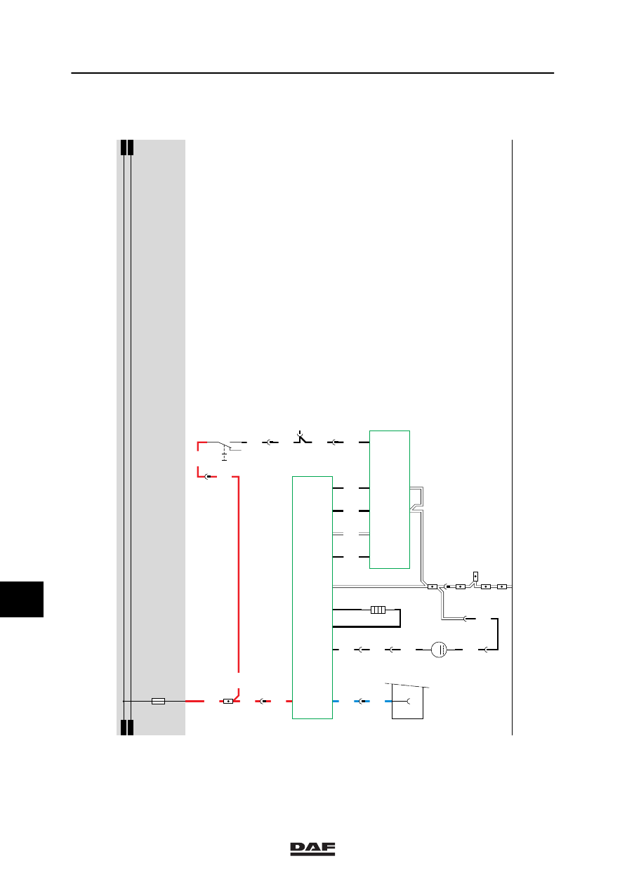
40. AUXILIARY HEATING - EBERSPÄCHER
The auxiliary air heating is a separate heating
which functions entirely independent of the
vehicle. The cab temperature is measured by a
temperature sensor which is installed in the
thermostat panel (E566). This sensor sends a
signal to the electronic unit which controls the
heating.
As a result, the cab temperature automatically
remains at the preset temperature. In that case,
the blower is in continuous operation.
OPERATION OF AUXILIARY HEATING
The auxiliary air heating van be activated using
the button on thermostat E566. It is possible to
use the thermostat in combination with a
programming clock. If this button is switched to
the “interior heating” position, the heating will be
activated. A green lamp will now light up in the
thermostat.
If the heating is activated, the auxiliary heating
unit (D871) activates the fan in the heating unit
(D871).
At the same time the fuel feed pump for the
auxiliary Eberspächer heating (B122) is
activated, so that the correct amount of fuel is
fed to the ignition chamber.
If the fuel is ignited, a temperature sensor
(installed in the thermostat) will apply a voltage
to the heating unit so that at a certain
temperature, the heating unit (D871) switches
off.
If the sensor measures a lower temperature
than the temperature preset by the driver (using
the temperature control button on the
thermostat), the heating power will be adjusted.
In the case of overheating, the thermal
protection will switch off the fuel pump. This will
switch off the heating.
10
ǹ 9711
5
ELECTRICAL INSTALLATION
Electrical installation
2-152
12
483
40
1316630/05
EL000141
34/402
1156
1156
1156
1
483
4939
9003
4941
5117
1156
3037
3037
11
483
4936
4936
6
483
4936
31
115
5116
4
483
5116
7
397
5116
15
483
5116
C778
5
71
0I
1156
5
380
1156
30
115
5
483
4935
4935
1
23456789
1
0
1
1
1
2
1
3
1
4
1
5
1
6
1
7
1
8
1
9
2
0
2
1
2
2
2
3
2
4
2
5
2
6
2
7
2
8
2
9
3
0
3
1
3
2
3
3
3
4
3
5
3
6
3
7
3
8
3
9
4
0
4
1
4
2
4
3
4
4
4
5
4
6
4
7
4
8
4
9
5
0
5
1
5
2
5
3
D878
1010
1000
1010
1000
E114
15A
A021
14
12/
269
3/
269
10/
269
14/
269
2/
269
E566
7/
269
11/
269
B122
M
2
1
B168
D871
5/
482
4/
482
3/
482
7/
482
6/
482
9/
482
13/
482
8/
482
14/
482
11/
482
10
ǹ 9711
5
Electrical installation
ELECTRICAL INSTALLATION
2-153
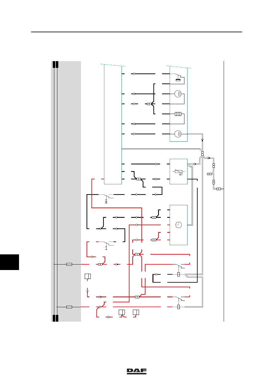
41. WEBASTO AUXILIARY HEATING, THERMO 90
VARIANTS
Location
78 Wire 4009 only applies in the case of a VF
engine.
SEE THE SYSTEM MANUAL FOR MORE
INFORMATION
10
ǹ 9711
5
ELECTRICAL INSTALLATION
Electrical installation
2-154
1316630/05
EL000152
41
1201
15/401
DVB
1201
C802
2
20
1201
1
376
C760
2
20
1201
DVB
1201
1201
C588
2
20
1
397
1201
1156
34/402
1156
1201
1156
1156
1
383
1156
1156
1156
1201
1156
1201
1201
5
380
1156
1156
1
478
1156
1156
1156
1156
1201
4660
15
380
4660
4660
7
397
4660
4690
4660
4660
4
383
3
478
4660
6
478
4892
4892
4892
9
478
6
478
4667
4668
4981
4981
4663
4981
4664
4981
11
145
1201
4666
4981
4
478
4980
5
478
4980
4980
4980
4666
5
145
4667
1
145
4668
4663
6
145
2
145
4664
E571
1
23
0I
4980
6
397
7
383
4980
4980
1156
1156
13
145
2
478
D878
1010
1000
E031
15A
1010
1000
E114
15A
1
23456789
1
0
1
1
1
2
1
3
1
4
1
5
1
6
1
7
1
8
1
9
2
0
2
1
2
2
2
3
2
4
2
5
2
6
2
7
2
8
2
9
3
0
3
1
3
2
3
3
3
4
3
5
3
6
3
7
3
8
3
9
4
0
4
1
4
2
4
3
4
4
4
5
4
6
4
7
4
8
4
9
5
0
5
1
5
2
5
3
G247
30
85
86
87A
8
7
G170
30
85
86
87A
8
7
5/
480
2/
480
4/
480
6/
480
7/
480
8/
480
E576
C778
5
71
0I
E565
2/
173
3/
173
7/
173
5/
173
M
M
B204
5/530
12/530
1/530
6/530
7/530
2/530
11/530
8/530
D827
3/
168
9/
167
1/
167
3/
167
7/
167
2/
167
6/
168
6/
167
1/
168
5/
168
10
ǹ 9711
Нет комментариевНе стесняйтесь поделиться с нами вашим ценным мнением.
Текст