DAF 95XF. Manual — part 133
6
Inspection and adjustment
BRAKE COMPONENTS
1-15
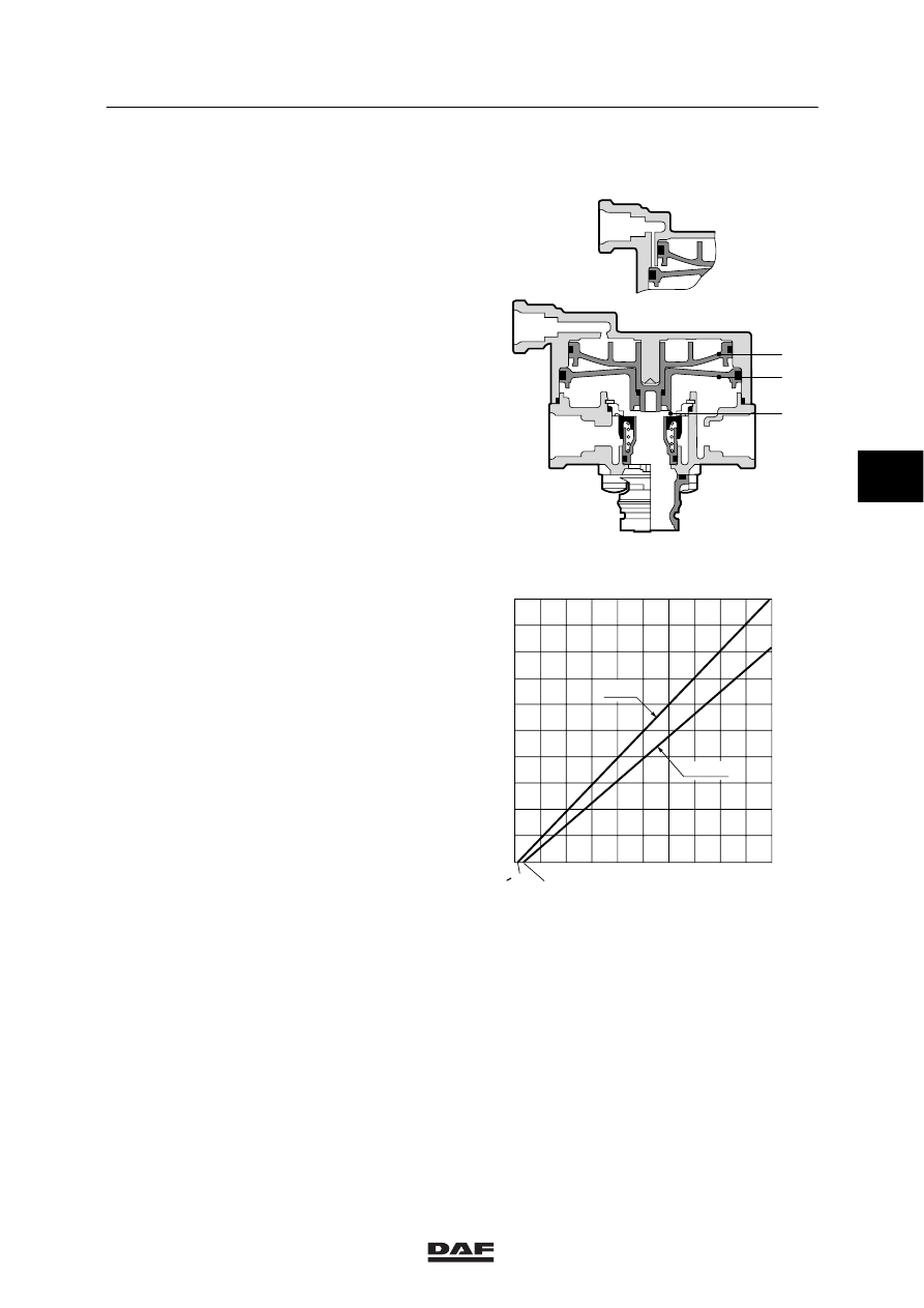
1.9 INSPECTION CHECK/RELAY VALVE
Checking the relay operation
1.
Ensure there is sufficient system pressure.
2.
Via a T-piece, connect a pressure gauge to
port (42) of the double check/relay valve,
and a pressure gauge to port (12) of the
spring-brake cylinder.
3.
Place the emergency parking brake valve in
the driving position, and check the reduced
output pressure from the double
check/relay valve to port (12) of the
spring-brake cylinder (see graph, line
P41 = 0 bar).
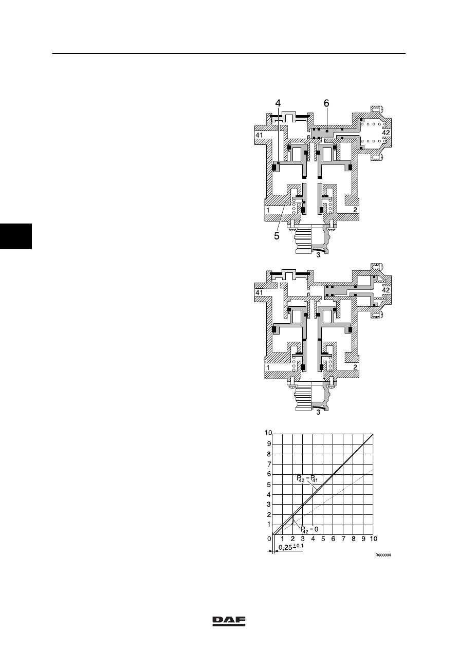
Checking non-increment function
1.
Ensure there is sufficient system pressure.
2.
Via a T-piece, connect a pressure gauge to
port (4) (test connection) of the
load-sensing valve, and a pressure gauge
to port (12) of the spring-brake cylinder.
3.
Set the parking brake valve in the parking
position.
4.
Slowly depress the brake pedal; both
gauges should indicate a similar pressure
increase (see graph, P42
≤41).
41
42
1
2
1
2
3
R600082
0
1
2
3
4
5
6
7
8
9
10
1
2
3
4
5
6
7
8
9
10
P
2
(bar)
P
41/42
(bar)
=
0.2
0.3
±
0.15
10
±
0.3
8.3
±
0.2
P
42
≤ 41
P
41 = 0 bar
R 600084
4
ǹ 0006
6
BRAKE COMPONENTS
Inspection and adjustment
1-16
1.10 INSPECTION EMPTY/LOAD RELAY VALVE
1.
Using a T-piece, connect a pressure gauge
to port (41).
2.
Connect a pressure gauge to the test
connection on one of the brake chambers
of the front axle.
3.
Connect a pressure gauge to the test
connection on one of the brake chambers
of the rear axle.
4.
Pressurise the system.
Testing when empty
5.
Set the load-sensing valve to the empty
position.
6.
Slowly depress the brake pedal.
The pressure increase on the front axle
should rise gradually, not in jumps.
The pressure at the front axle will increase
more gradually than at port (41). (An empty
vehicle will show a larger difference than a
partially loaded vehicle.)
Testing when fully loaded
7.
Set the load-sensing valve to the full-load
position.
8.
Slowly depress the brake pedal.
The pressure increase on the front axle
should rise gradually, not in jumps.
The pressure at the front axle will increase
as quickly (approx. 0.2 bar) as at port (41).
It should be possible to achieve system
pressure.
Testing when faulty
9.
Disconnect the line at port (42), and plug off
this line.
10. Repeat point 8.
11. Set the load-sensing valve as specified.
12. Reconnect the lines to ports (41) and (42),
as originally fitted.
13. Remove the pressure gauges.
4
ǹ 0006
6
Inspection and adjustment
BRAKE COMPONENTS
1-17
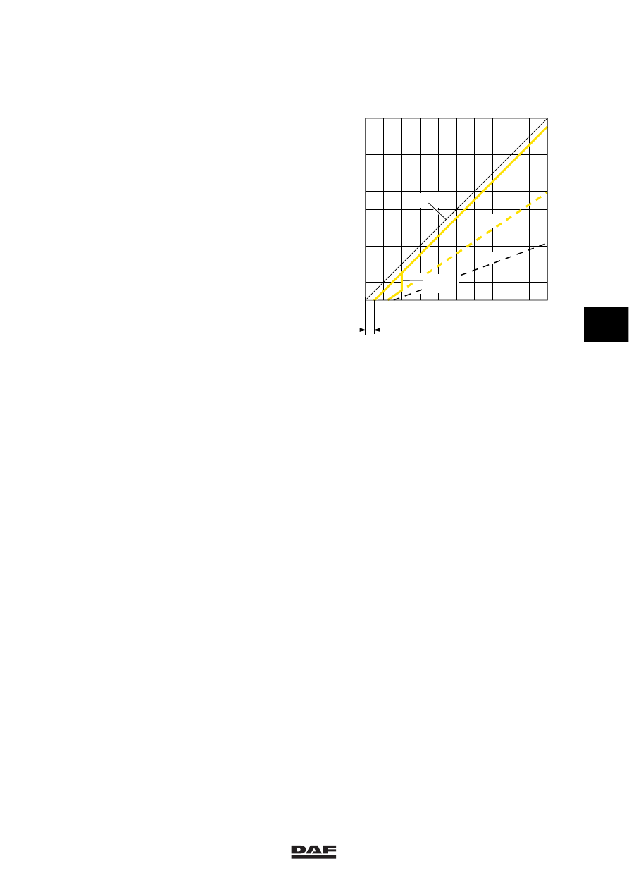
Checking the output pressure to the front
axle
1.
Measure the rear axle load.
2.
Check the setting of the load-sensing valve.
3.
Connect a pressure gauge to the test
connection for the load-sensing valve (input
pressure) and a pressure gauge to the test
connection on the spring-brake cylinder of
the front axle.
4.
Make sure that the reservoir pressure
exceeds 6.5 bar.
5.
Depress the brake pedal until the pressure
gauge on the test connection of the
load-sensing valve reads 6 bar, and read off
the braking pressure on the pressure gauge
on the front axle.
6.
Compare this value with the data on the
table, mounted on the door post.
0
0,1
0,5
1
1
2
2
3
3
4
4
5
5
6
6
7
7
8
8
9
9
10
10
+
_
P
0
42
=
P
42
P
41
=
1:2,7
1:1,5
41(bar)
p
2(bar)
p
R600339
Pressure reduction models with increase of
control pressure
4
ǹ 0006
6
BRAKE COMPONENTS
Inspection and adjustment
1-18
1.11 INSPECTION AND ADJUSTMENT, PRESSURE-LIMITING VALVE WITH
INTEGRATED NON-RETURN VALVE
Inspection pressure-limiting valve
1.
Place pressure gauges on ports (22) and
(23).
2.
Increase and decrease the pressure at port
(11) or (12) without exceeding the limiting
pressure; the gauge reading should rise
and fall simultaneously.
3.
Increase the pressure at port (11) or (12)
until it exceeds the limiting pressure; the
pressure gauge should indicate the limiting
pressure.
Adjust the pressure limiting valve, if
required.
Checking the non-return valve
1.
Place pressure gauges on ports (22) and
(23).
2.
Make sure that the reservoir pressure
exceeds 6.5 bar.
3.
Simulate a defect at port (21).
4.
The pressure gauge readings on both
pressure gauges (ports 22 and 23) should
not fall.
Adjustment pressure-limiting valve
1.
The pressure-limiting valve can be adjusted
with the adjustment screw.
R600226
11
2
3
6
5
12
23
21
22
1
4
4
ǹ 0006
Нет комментариевНе стесняйтесь поделиться с нами вашим ценным мнением.
Текст