DAF 95XF. Manual — part 131
6
Inspection and adjustment
BRAKE COMPONENTS
1-7
6.
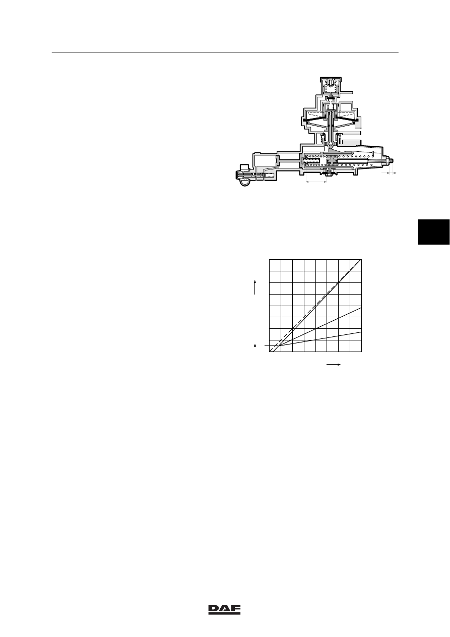
Set the simulated bellows pressure at its
highest value, as indicated on the
instruction plate. Depress the brake pedal
until gauge (4) indicates a pressure of 6
bar.
Read off pressure gauge (2) and check
whether this braking pressure matches the
pressure marked in the table on the
instruction plate.
If the braking pressure is incorrect, L2
should be adjusted.
Before attempting to change L2, first make
all connections pressureless.
-
Braking pressure too high: shorten L2
-
Braking pressure too low: extend L2
7.
Repeat the procedure described in point 6
until the measured braking pressure
reading is within the tolerance limits.
8.
Set the simulated bellows pressure at its
second lowest value, as indicated on the
instruction plate. Depress the brake pedal
until gauge (4) indicates a pressure of
6 bar.
Read off pressure gauge (2) and check
whether this braking pressure matches the
pressure marked in the table on the
instruction plate.
If the braking pressure is incorrect, L1
should be adjusted. This is possible without
removing the spring.
Insert a crosshead screw driver of sufficient
length into the hollow adjusting screw.
Before attempting to change L1, first make
all connections pressureless.
-
Braking pressure too high: extend L1
-
Braking pressure too low: shorten L1
9.
If L1 has been changed, repeat the
procedure from point 6.
R600120
41 42
2
1
L1
L2
0
1
2
3
4
5
6
7
8
1
2
3
4
5
6
7
8
P
4
(bar)
P
2
(bar)
0.5
0.1
P
41
P
41
=5.9 bar
P
41
P
42
=2.3 bar
P
41
P
42
=0.5 bar
W604025
4
ǹ 0006
6
BRAKE COMPONENTS
Inspection and adjustment
1-8
1.6 INSPECTION AND ADJUSTMENT, LOAD-SENSING VALVE, LEAF SPRINGS
Explanation of instruction plate
The data of the axle loads and the output
pressures are listed on the instruction plate per
axle from front to rear.
So “1” is the front axle, etc.
The data for the “driven axle” given on the
instruction plate are important when the
load-sensing valve is checked.
1.
Measure the rear axle load.
Note:
A load-sensing valve on a vehicle with a
leaf-sprung trailing axle should be adjusted
with the trailing axle lowered. When
adjusting the load-sensing valve, take the
weight of both axles.
2.
Check the attachment of the control lever
and its ease of operation.
3.
Also check whether the correct valve and
the correct spring assembly have been
fitted (for information, see the instruction
plate).
4.
Check length L of the control lever
(see instruction plate).
5.
Connect pressure gauge (1) to the test
connection (1) of the load-sensing valve
and pressure gauge (2) to the test
connection on one of the spring-brake
cylinders (service-brake connection) of the
rear axle.
6.
Make sure that the reservoir pressure
exceeds 6.5 bar.
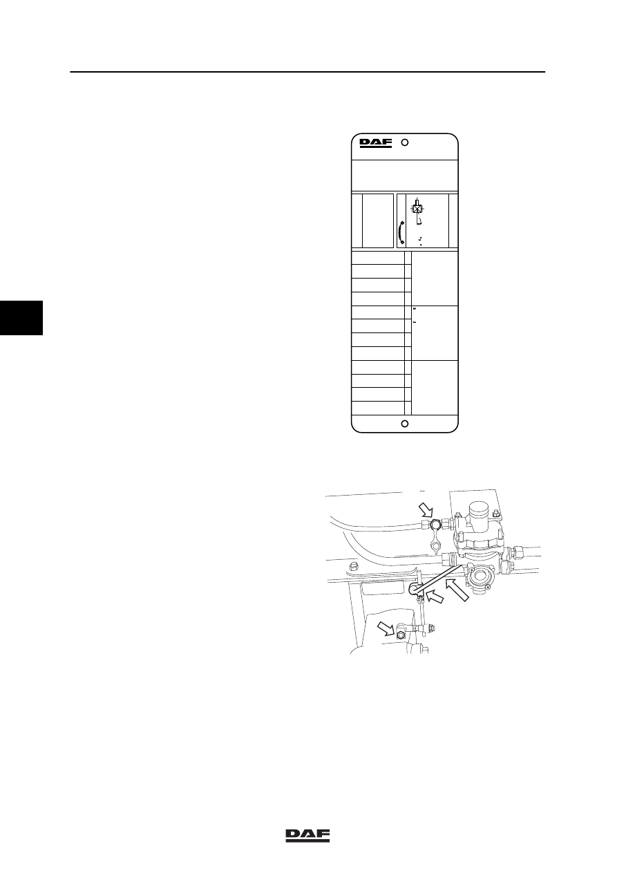
MEEREGELVENTIEL
EMPTY-LOAD VALVE
LAST-LEER VENTIEL
VALVE CHARGE-VIDE
VALVOLA VUOTO-CARICO
VALVULA VIDA-CARGA
ASLAST
AXLE LOAD
ACHSLAST
CHARGE SOUS ESSIEU
CARICO ASSE
CARGA EJE
UITGESTUURDE DRUK
DELIVERY PRESSURE
AUSGESTEUERTER DRUCK
PRESSION DELIVREE
PRESSIONE USCITA
PRESION DE SALIDA
G
p
2
BALGDRUK
PRESSURE BELLOWS
BALG DRUCK
PRESSION COUSSIN
PRESS.CUSCINI ARIA
PRESION FUELLES
p3
bar
b
ar
x 10
4
N
AUTOM. LASTAFHANKELIJKE REMKRACHTREGELING
AUTOM. LOAD SENSING DEVICE
AUTOM LASTABHANGIGE BREMSKRAFT REGELINR.
DISPOSITIF DE CORRECTION AUTOM DE FREINAGE
REGOLATORE AUTOM. DELLA FORZA FRENANTE
REGULADOR AUTOM. DEL ESFUERZO DE FRENADA
1261660
TYPE - TIPO : FA
KNR BR 4452
p1= > 6.5 bar
p4= 6.0 bar
0093778
2
1
2.0
2.5
3.0
4.0
5.0
10.0
11.0
11.5
2
1
1.7
1.9
2.2
2.9
3.5
5.5
5.8
6.0
4.4
4.5
4.6
4.9
5.2
5.9
6.0
6.0
0.2
0.4
p4
p1
L= 195 MM
G= 11.5
α
= 15 2
p2
L
i = 1 : 1.5
M6045
3
2 L
1
M6106
4
ǹ 0006
6
Inspection and adjustment
BRAKE COMPONENTS
1-9
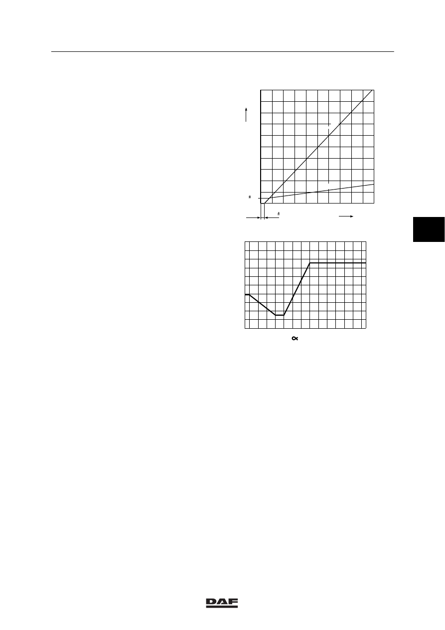
7.
Depress the brake pedal until pressure
gauge (1) reads 6 bar, and on pressure
gauge (2), read off the braking pressure of
the rear axle.
8.
Compare this value with the data on the
table, mounted on the door post.
9.
The braking pressure can be corrected by
moving the rubber socket (2) in relation to
the vertical connecting rod; do not adjust
length L of the control lever.
10. Also check whether the delivery pressure is
passed on practically unreduced under
maximum load. For this check remove ball
joint (3) and move the lever towards the
maximum load position.
0
1
2
3
4
5
6
7
8
9
10
1
2
3
4
5
6
7
8
9
10
0.5
P
4
(bar)
P
2
(bar)
0.1
0.3
0.2
1:1
1:8
W604027
1
0
2
3
4
5
6
7
8
9
10
0
-10
-20
-30
-40
-45
10
20
30
40
50
60
70
80
90 95
P
4
=7,5 bar
P
2
(bar)
R 600108
(
°)
4
ǹ 0006
6
BRAKE COMPONENTS
Inspection and adjustment
1-10
1.7 ADJUSTMENT OF THE LINKAGE MECHANISM OF THE LOAD-SENSING
VALVE WITH LEAF-SPRING TRAILING AXLE
Explanation of instruction plate
The data of the axle loads and the output
pressures are listed on the instruction plate per
axle from front to rear.
So “1” is the front axle, etc.
The data for the “driven axle” given on the
instruction plate are important when the
load-sensing valve is checked.
1.
Measure the axle loads of the driven axle
and the trailing axle, with the trailing axle
lowered.
2.
Check the attachment of the control lever
and its ease of operation.
3.
Also check whether the correct valve and
the correct spring assembly have been
fitted (for information, see the instruction
plate).
4.
Check length L of the control lever (see
instruction plate).
5.
Connect pressure gauge to the test
connection (1) of the load-sensing valve
and pressure gauge to the test connection
on one of the spring-brake cylinders
(service-brake connection) of the rear axle.
6.
Make sure that the reservoir pressure
exceeds 6.5 bar.
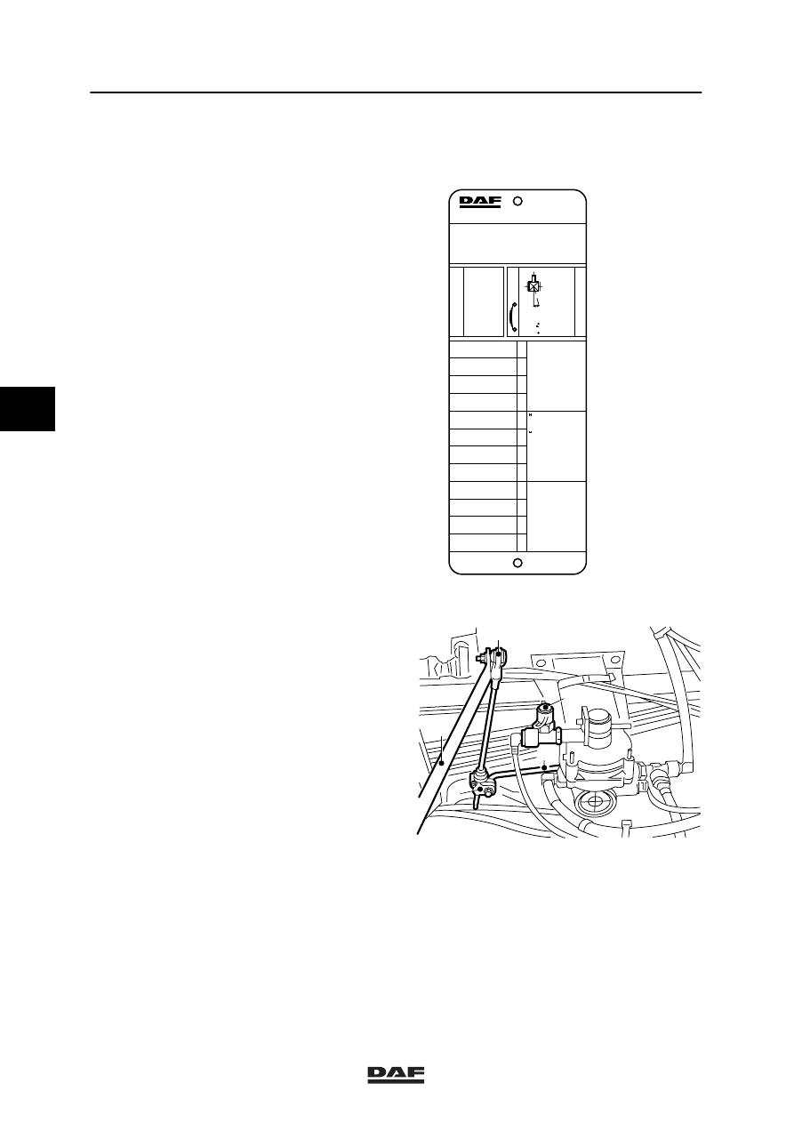
MEEREGELVENTIEL
EMPTY-LOAD VALVE
LAST-LEER VENTIEL
VALVE CHARGE-VIDE
VALVOLA VUOTO-CARICO
VALVULA VIDA-CARGA
ASLAST
AXLE LOAD
ACHSLAST
CHARGE SOUS ESSIEU
CARICO ASSE
CARGA EJE
UITGESTUURDE DRUK
DELIVERY PRESSURE
AUSGESTEUERTER DRUCK
PRESSION DELIVREE
PRESSIONE USCITA
PRESION DE SALIDA
G
p
2
BALGDRUK
PRESSURE BELLOWS
BALG DRUCK
PRESSION COUSSIN
PRESS.CUSCINI ARIA
PRESION FUELLES
p3
bar
b
ar
x 10
4
N
AUTOM. LASTAFHANKELIJKE REMKRACHTREGELING
AUTOM. LOAD SENSING DEVICE
AUTOM LASTABHANGIGE BREMSKRAFT REGELINR.
DISPOSITIF DE CORRECTION AUTOM DE FREINAGE
REGOLATORE AUTOM. DELLA FORZA FRENANTE
REGULADOR AUTOM. DEL ESFUERZO DE FRENADA
1261660
TYPE - TIPO : FAS
KNR BR 4452
p1= > 6.5 bar
p4= 6.0 bar
0093778
2+3
1
3.5
4.0
5.0
6.0
16.0
18.0
18.8
20.0
2+3
1
1.5
1.5
1.8
2.8
4.8
5.4
5.7
6.0
4.4
4.5
4.6
4.9
5.2
5.9
6.0
6.0
0.2
0.4
p4
p1
L= 195 MM
G= 11.5
α
= 15 2
p2
L
i = 1 : 1.5
R600326
R600327
L
4
3
1
2
4
ǹ 0006
Нет комментариевНе стесняйтесь поделиться с нами вашим ценным мнением.
Текст