DAF 95XF. Manual — part 288
5
Electrical installation
ELECTRICAL INSTALLATION
2-51
F033
4
2
6
1316630/05
EL000102
3400
3401
14/401
1211
1211
F087
1
38
3410
D853
B9
7
3403
32
115
3438
8
118
3438
3438
4
118
2/202
8/202
7/200
3/200
15/200
1/202
8/200
D550
7
5
D550
34
5
F000
1
28
12
115
3410
D
115
3402
F000
2
28
9/200
5/200
2152
G005
87
11
C025
1
11
2152
9
115
2152
2/200
12/400
3402
D721
1
28
3402
6/200
3420
16/200
D550
38
5
3420
6
465
G284
5
25
3420
11/200
4019
3/202
19
114
E112
2
3
4019
3408
9/202
10
115
F006
2
15
3408
2122
7/202
E006
2
10
2122
6
281
C002
1
10
2122
20/200
1211
15/201
D853 B14
7
D851
25
34
3432
4/200
4
373
3432
!
!
3410
1211
1211
1211
14/400
3410
3410
16/400
1211
D806
1
27
1211
D591
19
28
3452
13/400
54
55
56
57
58
59
60
61
62
63
64
65
66
67
68
69
70
71
72
73
74
75
76
77
78
79
80
81
82
83
84
85
86
87
88
89
90
91
92
93
94
96
96
97
98
99
100
101
102
103
104
105
106
D878
1010
1000
1010
1000
E035
10A
3
2
1
45
G240
1211
3402
3402
D852
M
L
!
P
STOP
10
ǹ 9711
5
ELECTRICAL INSTALLATION
Electrical installation
2-52
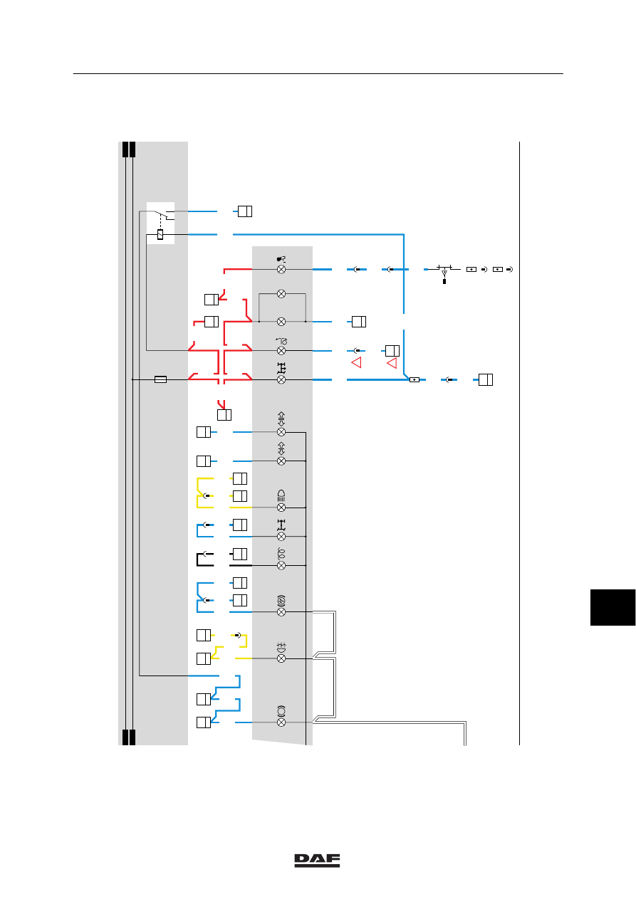
7.
C.W.S.-2
CWS is the abbreviation for Central Warning
System.
The system consists of an electronic unit (D853)
and a digital display. The display is used to
display error warnings using symbols.
The CWS is connected using two (2) black
connectors.
Connector 395 (21-pin) and connector 396 (15
pin).
Red warning symbol
Function
Connector + contact
Wire number
air system storage pressure too low
395/9
3426
steering circuit
395/8
3518
engine oil pressure too low
395/10
3014
coolant temperature too high
396/2
3012
coolant level too low
396/3
3036
alternator charging current too high
(
> 30 0.5 V)
396/6
1020
alternator charging current too low
(
> 20 0.5 V)
396/6
1020
cab not locked
395/11
3492
engine management
395/14
3435
Orange warning symbol
coolant level
395/5
3022
retarder malfunction
395/12
3417
truck ABS malfunction
395/6
3427
engine management malfunction
395/14
3435
trailer ABS malfunction
395/7
3428
ECAS malfunction
395/20
3431
blocked air filter
395/3
3017
fuel level (too) low
395/2
3413
AGS malfunction
395/4
3469
HGS fluid level (delayed switch)
395/19
3474
ASC
395/17
3471
10
ǹ 9711
5
Electrical installation
ELECTRICAL INSTALLATION
2-53
CONNECTOR POINTS CWS-2 UNIT
CONNECTOR 395
Pin
No.
Designation
Wire
number
1
Interconnection to connector 396, pin 10.
3406
2
Input for alarm function “Fuel supply on reserve”. Activated if the fuel supply
meter reaches the red area. The instrument panel connects point A2 to earth.
3413
3
Input for alarm function “Fuel filter blocked”. Activated if pneumatic switch F016
closes and pin 1 is connected to earth. If the input is 0 V (earth), the light
concerned will light up.
3017
4
Input for alarm function “Lubricating system”. Activated in the case of a
malfunction. The AGS unit supplies a voltage to the CWS unit and will activate
the light on the CWS panel.
3469
5
Daily check.
If the input is connected to earth, the symbol will light up.
3022
6
Input for alarm function “ABS truck malfunction”. Activated if the truck ABS
system malfunctions. If the input is 0 V (earth), the light concerned will light up.
3427
7
Input for alarm function “ABS trailer malfunction”. If the input is 0 V (earth), the
light concerned will light up.
3428
8
Input for alarm function “Emergency circuit steering system” first (1st) circuit.
Activated if fluid passage switch F047 closes and pin 2 is connected to earth. If
the input is 0 V (earth), the light concerned will light up.
3518
9
Input for alarm function “Brake reservoir pressure”. Activated if the brake
reservoir pressure is too low (switch at reservoir pressure meter closed).
3426
10
Input for alarm function “Oil pressure”. Activated if pressure switch F011 closes
as a result of an insufficient oil pressure. If the input is 0 V (earth), the light
concerned will light up.
3014
11
Input for alarm function “Cab lock”.
Activated if switch F009 is closed.
If the input is 0 V (earth), the light concerned will light up.
3492
12
Input for alarm function “Retarder”.
3417
14
Input for alarm function “Engine management”.
Orange symbol: less serious malfunction.
Red symbol: serious malfunction.
3435
17
Input ABS/ASC (D586).
This lamp: blinks a few times when switching on the contact if the ABS/ASC
traction switch (C737) is activated and lights up continuously if a malfunction
occurs in this control.
3471
19
Input for alarm function “Fluid level HGS”. Activated if switch F076 closes
because the level is too low. If the input is 0 V (earth), the light concerned will
light up after eight (8) seconds.
3474
20
Input for alarm function “ECAS defective”.
3431
10
ǹ 9711
5
ELECTRICAL INSTALLATION
Electrical installation
2-54
CONNECTOR 396
Pin
No.
Designation
Wire
number
1
Activation switch “I”, more warnings.
3490
2
Input for alarm function “Coolant temperature too high”.
The signal on this input originates from the instrument panel DIP 2 (D816). If
the input is 0 V (earth), the light concerned will light up.
3012
3
Coolant level too low. If the level is too low, the switch closes and the symbol
lights up.
3036
5
Door on driver’s side open/closed.
2600
6
Input D
+ for alarm functions “Generator voltage too high/too low”.
Generator voltage too low:
If D+ is
< 21 1V, the alarm function is activated. Generator voltage too high:
If D+ is
> 30 1V, the alarm function is activated. The input receives its analog
signal from D+ from the generator.
1020
9
Output central warning lamp (D004) red.
The CWS unit will activate the lamp if a malfunction has been detected which
must be repaired as soon as possible. The only exception to this rule is the
malfunction signal: alternator voltage too low.
If the input is 0 V (earth), the red light on the CWS panel will light up.
3403
10
Interconnection to connector 395, pin 1.
3406
12
Connection for control lighting.
2630
13
Earth connection.
M
14
Supply connection behind contact.
1211
15
Supply connection in front of contact.
1101
10
ǹ 9711
Нет комментариевНе стесняйтесь поделиться с нами вашим ценным мнением.
Текст