DAF 95XF. Manual — part 286
5
Electrical installation
ELECTRICAL INSTALLATION
2-43
4.
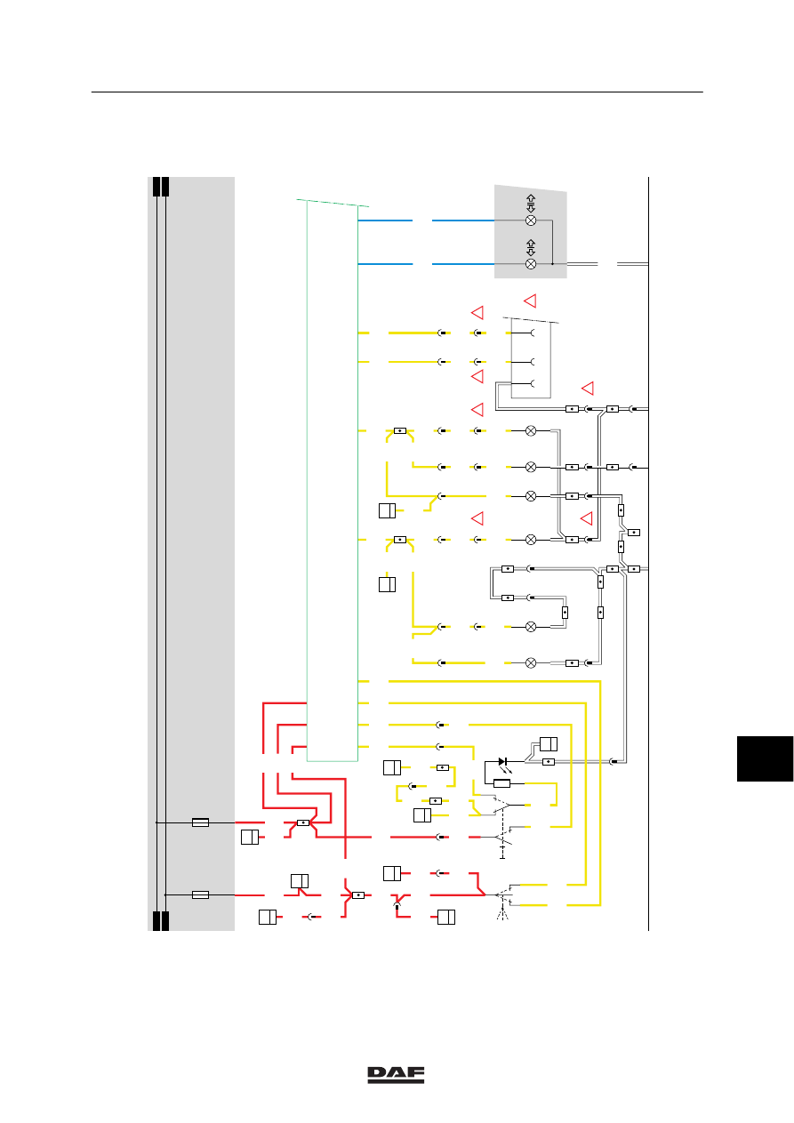
DIRECTION INDICATORS AND WARNING LIGHTS
WARNING LIGHTS
A supply voltage is applied to connection point 6
of warning-light switch C765 through fuse E108.
By activating the warning light/direction indicator
switch the supply voltage is applied to point 37 of
the CTE-2.
The CTE 2 now supplies a square-block voltage
through point 4 to lights C014, C016 and C018 (all
on the left side) and through point 31 to C015,
C017 and C019 (all on the right side), as a result
of which these lights start blinking simultaneously.
The warning lights also function if the contact is
not activated.
CTE-2 (point 35) also supplies a square-block
voltage to warning light/direction indicator switch
C765 ( to point 1), causing the LED in the switch
to blink also.
DIRECTION INDICATORS
Left
If the direction indicator switch (C775) is activated
to the left (connection between points 3 and 2),
the supply voltage is passed on to point 53 of the
CTE-2 through wire 2002. Subsequently the
CTE-2 supplies a square-wave signal through
point 4 to C014, C016 and C018 (left direction
indicators) and through point 2 to connector
socket A000 pin 3 (in the case of an FA) or A002
pin 3 (in the case of an FT). Every time a pulse is
supplied to point 4 of the CTE-2, the lights will
blink briefly.
Right
If the direction indicator switch (C775) is activated
to the right (connection between points 3 and 1),
the supply voltage is passed on to point 24 of the
CTE-2 through wire 2001.
Subsequently the CTE-2 supplies a square-wave
signal through point 31 to C015, C017 and C019
(right direction indicators) and through point 30 to
connector socket A000 pin 5 (in the case of an
FA) or A002 pin 5 (in the case of an FT). Every
time a pulse is supplied to point 31 of the CTE-2,
the lights will blink briefly.
The CTE-2 (points 7 and 34) also supplies a
signal to the instrument panel.
If the direction indicator installation functions
properly, the lights for the truck (2/202) and the
trailer (8/202) will light up.
10
ǹ 9711
5
ELECTRICAL INSTALLATION
Electrical installation
2-44
VARIANTS
Location
29,37,38,43,42
Connector 495 is only used in
the case of an FA. Connector
493 is used in the case of an
FT.
44
Connector A000 is used for
an FA, connector A002 for an
FT.
SEE THE SYSTEM MANUAL FOR MORE
INFORMATION
10
ǹ 9711
5
Electrical installation
ELECTRICAL INSTALLATION
2-45
4
1316630/05
EL000098
1202
16/401
3
115
2006
1202
3/408
2/408
1/408
1114
A040
2
42
2006
1
495
2006
C018
1
8
2006
C017
1
2
C015
1
2
C016
1
2
C014
1
2
2006
!
!
C019
1
2
3401
3400
2008
2009
12
495
!
!
2003
2000
2001
2002
2000
2001
2002
1
23456789
1
0
1
1
1
2
1
3
1
4
1
5
1
6
1
7
1
8
1
9
2
0
2
1
2
2
2
3
2
4
2
5
2
6
2
7
2
8
2
9
3
0
3
1
3
2
3
3
3
4
3
5
3
6
3
7
3
8
3
9
4
0
4
1
4
2
4
3
4
4
4
5
4
6
4
7
4
8
4
9
5
0
5
1
5
2
5
3
1114
A040
1
42
1114
32/402
1114
1114
4
380
1114
C813
1
13
1202
1202
1202
30
114
E550
1
5
1202
1202
2
176
2029
C737
1
23
1202
C726
5
3
1202
5
185
E564
2
5
C737
A
23
1202
1202
2630
8
380
2003
2630
2630
12
380
E117
2
19
2630
2630
7
380
2000
2
281
2006
2006
1
284
2006
8
185
2006
4
115
2007
2007
2
495
2007
2007
!
2
286
2
288
2007
2007
2007
5
187
2007
2007
2007
12
284
18
281
21
380
21
185
12
288
11
495
18
286
D
115
12
187
A040
3
42
2006
6
115
4
495
2009
2009
!
5
115
3
495
2008
2008
!
9025
2/202
20/202
8/202
D852
M
D878
1010
1000
1010
1000
E019
10A
E108
15A
4/
232
D550
35/
232
37/
232
24/
232
53/
232
7/
232
34/
232
2/
232
30/
232
1/
232
42/
232
29/
232
31/
232
A000
13
5
C775
R
L
01
C765
A
B
25
1
7
6
10
ǹ 9711
5
ELECTRICAL INSTALLATION
Electrical installation
2-46
5
CTE-2
VARIANTS
Location
22,29
Connector 495 is only used in the case
of an FA.
Connector 493 is used in the case of
an FT.
44
Wire 4009 only applies in the case of a
VF engine.
102
DVB: Only applies in the case of a VF
engine.
SEE THE SYSTEM MANUAL FOR MORE
INFORMATION
10
ǹ 9711
Нет комментариевНе стесняйтесь поделиться с нами вашим ценным мнением.
Текст