DAF 95XF. Manual — part 247
5
Reading the circuit diagram
READING DIAGRAMS
3-1
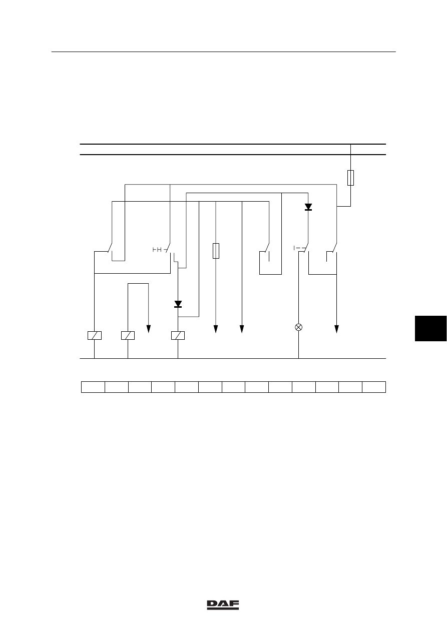
3. READING THE CIRCUIT DIAGRAM
A circuit diagram is intended to represent a
circuit as simply as possible with the aid of
symbols.
Use is made of symbols here.
58
59
60
61
62
63
64
65
66
67
68
69
70
1000
1010
M
LIGHT SWITCH
SWITCH MAIN/ DIPPED BEAM
G107
C622
1101
5.0A
D609
G000
85
86
G107
85
86
G154
85
86
E002
1020
2105
2630
21
10
2100
2
111
2120
E084
2154
59 30
2
2
1
1
2
7.5A
1
2
4
1
87
G154
C506
D610
58
30
87
143
205
251
009
039
052
146
LAMP
MAIN
SWITCH
M
68
W
59
V
65
87A
87A
G000
61
30
3.4
2
1
87
3.5
87A
E500145
1.
The diagram contains the indications “1000”
and “1010” at the top left.
These indications have the following
meaning:
1000 = power before contact.
1010 = power after contact.
2.
The diagram contains the letter “M” at the
bottom left.
This has the following meaning:
M = earth connection.
7
ǹ 9711
5
READING DIAGRAMS
Reading the circuit diagram
3-2
3.
To make it easier to find your way in the
circuit diagram, a “search bar” is included at
the bottom, which contains numbers.
These numbers are called location
numbers.
The legend of the circuit diagram contains
behind the description of the elementary
code number (ECN), the location number.
This makes it possible to find the location of
a component in the diagram.
4.
There is an arrow above the location
number 60, 63, 64, and 68 in the diagram
example.
At the bottom of this arrow is a number.
This number refers to the location number
on the search bar where you may find the
wire number concerned.
5.
Under the earth connection line (indicated
by the letter M), there are the letter V,
referring to relay G154, the letter W,
referring to relay G107, and the letter M,
referring to relay G000.
The meaning of these letters is given
below:
V = breaker contact
W = make-and-break contact
M = make-contact
These contacts can be found at the location
numbers shown under the letters “V”, “W”
and “M”.
The numbers shown under the relay codes
at the relay contacts in the diagram refer to
the location numbers on the reference bar
where the relays can be found.
6.
The circuit diagram shows the basic codes
(for instance, E002). The descriptions
referring to the basic codes are given in the
legend to the circuit diagram concerned.
7
ǹ 9711
5
Reading the circuit diagram
READING DIAGRAMS
3-3
7.
If there are no changes in the wire
numbers, these numbers are not repeated
in the diagram.
In the diagram example, wire 1101, for
instance is connected to point 87 of relay
contact G107, but also to point 2 of
component C622.
Wire 2100 (at location number 64) is
connected to point 30 of relay G154 but
also to point 85 of relay G000, etc.
1
2
3
7
4
P
6
Q
8
8
9
8
5
10
11
21
12
13
17
14
16
18
19
15
20
µP
E500135
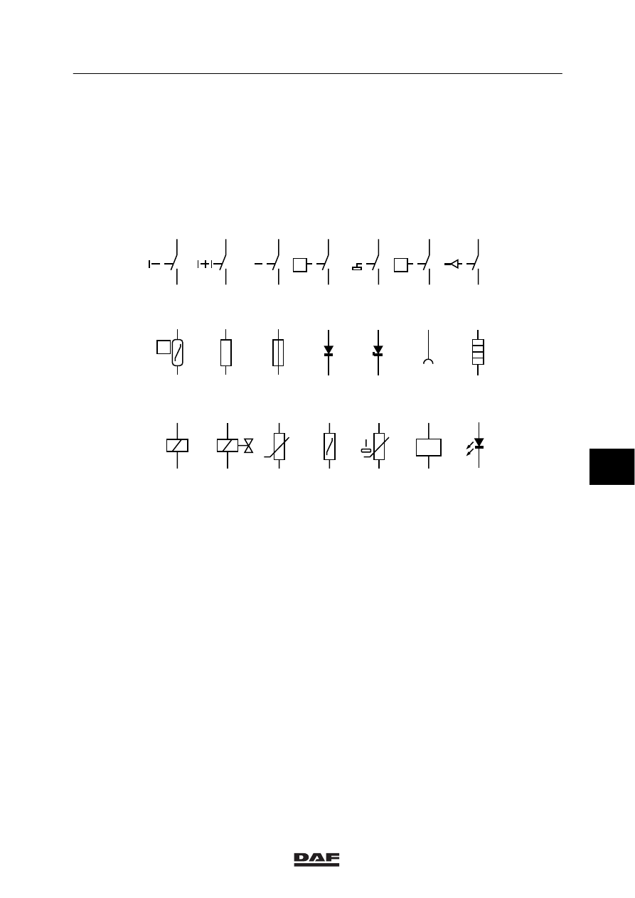
Symbols used
1.
Switch, manually controlled
2.
Switch (multi-position), manually controlled
3.
Switch (return), manually controlled
4.
Switch, pressure-controlled (pneumatically
or hydraulically)
5.
Switch, float position
6.
Switch, fluid through-flow
7.
Pressure switch
8.
Switch, temperature-dependent
9.
Resistor
10. Fuse
11.
Diode
12. Zener diode
13. Contact socket (e.g. connection of trailer)
14. Heating element
15. Relay
16. Electropneumatic valve
17. Resistor, voltage-dependent
18. Resistor, temperature-dependent
19. Resistor, fluid level-dependent
20. Microprocessor
21. LED
7
ǹ 9711
5
READING DIAGRAMS
Reading the circuit diagram
3-4
7
ǹ 9711
Нет комментариевНе стесняйтесь поделиться с нами вашим ценным мнением.
Текст