DAF 95XF. Manual — part 245
5
Connecting accessories
CONNECTING ACCESSORIES
1-15
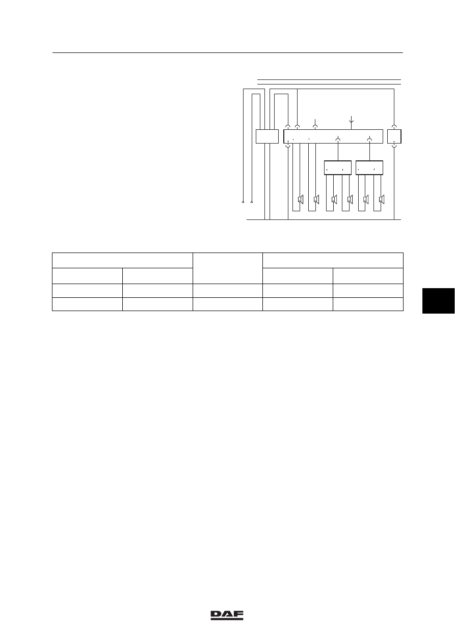
Channel memory of Grundig radio
The 12V/10 (20)A output is the supply voltage
for the channel memory (output A4 of the
converter).
+
4832
4831
R1+
R1
B180
+
4834
4833
R2+
R2
B181
B187
B026
12V
+
4828
4827
L1+
L1
B178
+
4541
4543
R+
R
B025
+
4540
4542
L+
L
12V
B
7
B024
+
4830
4829
L2+
L2
B179
B186
B185
D895
12V
24V
1108
1353
2
1
4
6
1000
1010
B1
A4
B2
A3
A1
A2
301 033
M
1
107
1
106
E500731
Note:
Input
Voltage
before/after the
Output
24 V
Wire no.
before/after the
contact
12 V
Wire no.
A2
1107
before
A4
1108
B2
1106
after
B1
1353
Wire 1105 is connected in contact/starter switch
position with relay G178: “accessories”.
Wires 1107 and 1106 on the converter wiring
harness should be reversed. (see figure)
6
ǹ 0009
5
CONNECTING ACCESSORIES
Connecting accessories
1-16
6
ǹ 0009
5
Contents
READING DIAGRAMS
1
CONTENTS
Page
Date
1.
LIST OF ABBREVIATIONS
1-1
9711
. . . . . . . . . . . . . . . . . . . . . . . . . . . . . . . . . . . . . . . . . . . . .
. . . . . .
2.
MARKING OF ELECTRIC WIRING
2-1
9711
. . . . . . . . . . . . . . . . . . . . . . . . . . . . . . . . . . . . . . .
. . . . . .
3.
READING THE CIRCUIT DIAGRAM
3-1
9711
. . . . . . . . . . . . . . . . . . . . . . . . . . . . . . . . . . . . . .
. . . . . .
4.
READING THE SUBDIAGRAM
4-1
9711
. . . . . . . . . . . . . . . . . . . . . . . . . . . . . . . . . . . . . . . . . .
. . . . . .
7
ǹ 9711
5
READING DIAGRAMS
Contents
2
7
ǹ 9711
Нет комментариевНе стесняйтесь поделиться с нами вашим ценным мнением.
Текст