DAF 95XF. Manual — part 791
1
TECHNICAL DATA
Internal and external cab components
1-16
1.2 TIGHTENING TORQUES
The tightening torques stated in this section are
different from the standard tightening torques
included in the overview of standard tightening
torques. Any other threaded connections that
are not specified must therefore be tightened to
the tightening torque stated in the overview of
standard tightening torques.
When attachment bolts and nuts are to be
replaced, it is important that they are of exactly
the same length and property class as the ones
removed, unless stated otherwise.
Windscreen wiper unit
Motor shaft nut
38 Nm
Windscreen wiper arm nut
18 Nm
Windscreen wiper arm bracket lock nut M20
18 Nm
Threaded holes in bulkhead
windscreen wiper arm bracket
silicone sealant
Clutch pedal
Sealant for end of clutch pedal spindle
silicone sealant
Recessed locking bolt
according to standard
(1)
Steering column
Universal joint attachment bolts
54 Nm
(2)
Steering wheel attachment nut
65 Nm
Door
Door limiter attachment nut M6
10 Nm
Hinge attachment bolts
30 Nm
Lock plate attachment bolts
18 Nm
(1)
Striker plate (cab)
23 Nm
Window crank attachment screw
according to standard
(1)
Grille
Grille--side hinge attachment bolts
15 Nm
Threaded holes in bulkhead
Hinge on cab side
silicone sealant
Exterior mirrors
Pavement mirror adjusting nut
7.0 - 8.1 Nm
Model with integrated arm:
attachment nut M8 for lower pivoting point of
D-shaped arm:
-
driver’s side
22 Nm
-
co--driver’s side
27 Nm
0
ᓻ 200345
0
1
Internal and external cab components
TECHNICAL DATA
1-17
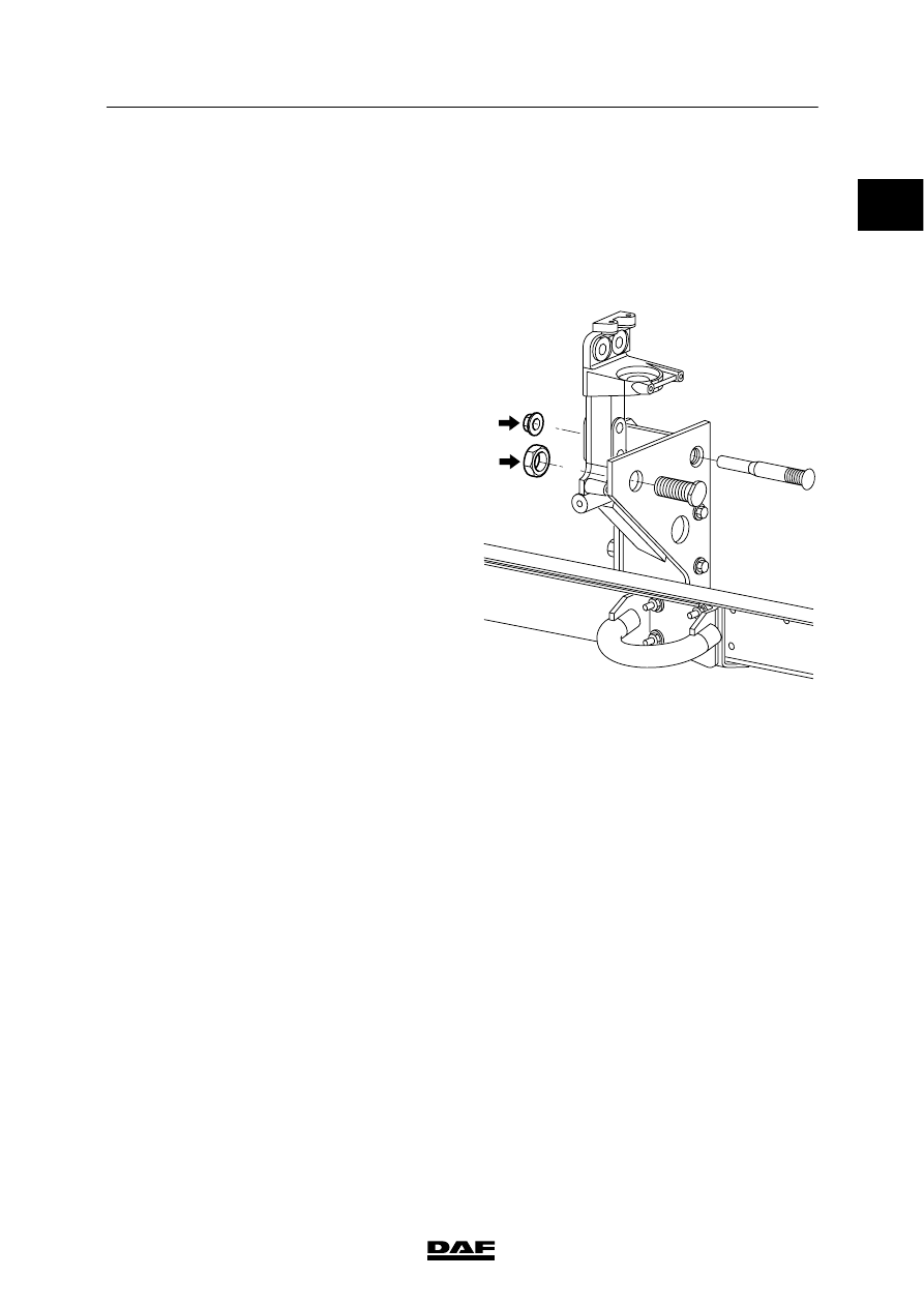
Front Underrun Protection leaf--sprung
model (without towing device)
Attachment bolt A
170
ᐔ 15 Nm
(1)
Attachment bolt B
170
ᐔ 15 Nm
(1)
(with towing device)
Attachment bolt A
170
ᐔ 15 Nm
(1)
Attachment bolt B
260 Nm
(1)
(1)
Secure with Loctite 243
(2)
Always replace the attachment bolt and nut
K100822
A
B
ᓻ 200345
1
TECHNICAL DATA
Internal and external cab components
1-18
0
ᓻ 200345
0
1
Cab suspension
TECHNICAL DATA
2-1
2. CAB SUSPENSION
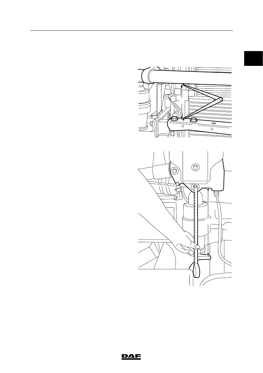
2.1 GENERAL
The F249 cab is mounted to the chassis at four
points with adjustable coil spring or air
suspension elements. These have integral
shock absorbers.
Adjustment dimensions of cab with coil
spring/air suspension elements
Size A
ᐔ 5 mm
227.7 mm
Size B
ᐔ 5 mm
272.5 mm
Size A:
distance between top of front
cross member and bottom of
stabiliser
Size B:
distance from top of suspension
bracket to centre of cab
lock/suspension bolt
Note:
Measurements for unloaded cab and normal
system pressure
The coil spring elements can be adjusted in 4
steps of 3 mm.
Spring distance of coil spring and air
suspension elements:
Front
approx. 80 mm (+40/-40)
Rear
approx. 64 mm (+32/-32)
K100348
A
K100349
B
ᓻ 200345
Нет комментариевНе стесняйтесь поделиться с нами вашим ценным мнением.
Текст