DAF 95XF. Manual — part 296
5
Electrical installation
ELECTRICAL INSTALLATION
2-83
17
1316630/05
EL000116
1107
2609
2600
1107
1107
C735
5
71
0I
3
C130
21
2617
12
189
2617
2617
11
380
3
C139
21
2617
B175
4
36
3
C149
12
2632
D709
1
2
3
C148
12
2633
12
190
2637
2637
D708
1
2
2637
2609
11
190
2633
2633
2611
9
380
2611
2612
10
380
2612
2611
11
189
2612
C732
5
71
0I
C731
71
5
0I
2633
1107
1107
1107
1107
10
189
D710
1
2
2610
2610
10
190
2632
2644
13
380
2644
2645
14
380
2645
2644
15
189
2645
C734
5
71
0I
C733
71
5
0I
2632
1107
14
189
9
190
2610
2632
2632
2632
2600
2610
9
189
2610
D878
1010
1000
1010
1000
54
55
56
57
58
59
60
61
62
63
64
65
66
67
68
69
70
71
72
73
74
75
76
77
78
79
80
81
82
83
84
85
86
87
88
89
90
91
92
93
94
96
96
97
98
99
100
101
102
103
104
105
106
3500
B501
3/
225
27/
232
17/
232
18/
232
D550
!
10
ǹ 9711
5
ELECTRICAL INSTALLATION
Electrical installation
2-84
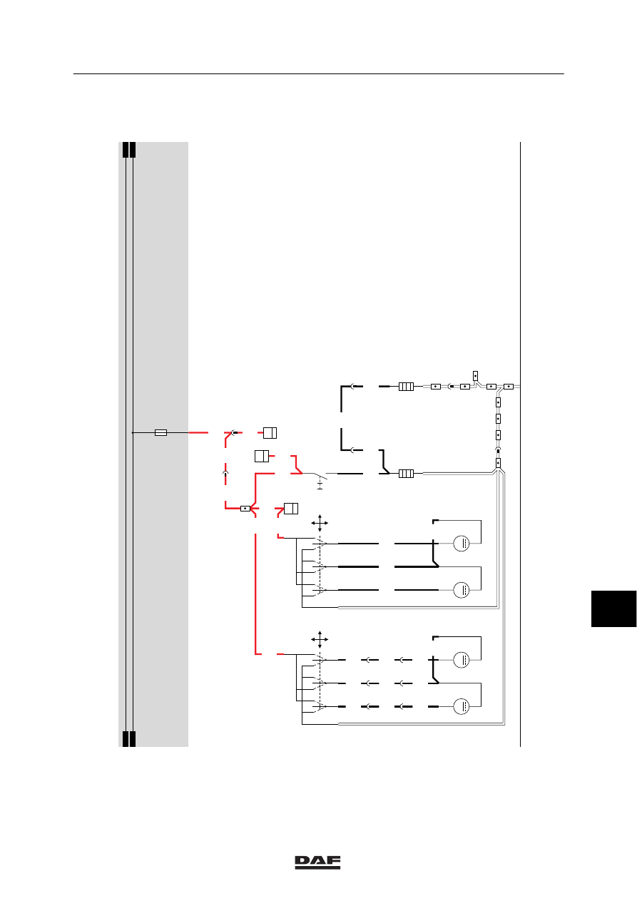
18. MIRROR HEATING AND MIRROR ADJUSTMENT
MIRROR HEATING
If the mirror heating switch (C746) is engaged, a
voltage is applied to both heating elements
B017 (driver’s side) and B018 (co-driver’s side)
through fuse E044, wire 1208 and switch C746.
The mirror heating can only be engaged if the
contact relay is activated.
MIRROR ADJUSTMENT
The outside mirrors are adjusted using two
so-called “joystick” switches C695 (driver’s side)
and C696 (co-driver’s side). If the joystick is
moved from its rest position (centre) into a
certain direction, a voltage is applied to the
mirror-adjustment motor B005 (driver’s side) or
B006 (co-driver’s side) and the mirror concerned
will follow this movement.
The voltage for the left/right mirror adjustment
motor is supplied through wires 4770 and 4774
(driver’s side) or wires 4771 and 4775
(co-driver’s side). The voltage for the up/down
mirror adjustment motor is supplied through
wires 4772 and 4774 (driver’s side) or wires
4773 and 4775 (co-driver’s side).
10
ǹ 9711
5
Electrical installation
ELECTRICAL INSTALLATION
2-85
18
1316630/05
EL000117
1208
26/400
9
196
6
277
B006
4771
1
277
4771
1
197
4771
4775
4775
4775
4773
4773
4773
3
277
3
197
2
277
2
197
4775
B005
4772
4774
4770
4774
1208
C744
4
36
1208
1208
1208
C743
4
36
1208
2
276
1208
2
196
1208
1208
4532
4532
4532
9
276
4532
C745
4
36
1208
6
197
D878
1010
1000
1010
1000
E044
10A
1
23456789
1
0
1
1
1
2
1
3
1
4
1
5
1
6
1
7
1
8
1
9
2
0
2
1
2
2
2
3
2
4
2
5
2
6
2
7
2
8
2
9
3
0
3
1
3
2
3
3
3
4
3
5
3
6
3
7
3
8
3
9
4
0
4
1
4
2
4
3
4
4
4
5
4
6
4
7
4
8
4
9
5
0
5
1
5
2
5
3
M
1
Y
M
2
X
4
3
4
13
5
2
X1
Y1
Y1
X1
C696
M
1
Y
M
2
X
4
3
4
13
5
2
X1
Y1
Y1
X1
C695
B017
2
1
B018
2
1
C746
1
2
0I
10
ǹ 9711
5
ELECTRICAL INSTALLATION
Electrical installation
2-86
19. CONTROL LIGHTING
CONTROL LIGHTING
The control lighting consists of the lamps and
LEDs in the various function switches.
When the lighting switch (C622) is being
operated, a supply voltage will be applied to
relay G000 through fuse E084 and lighting
switch (C622), wire 2100.
Relay G000 is activated so that a voltage is
applied to the control lighting (wire 2630)
through fuse E117, causing it to light up.
When switch C622 is being operated, the
following lamps will light up:
B030, C072, C760, C802 (so-called functional
lighting).
The following switches will cause a LED to light
up:
C725, C726, C727, C731, C733, C734, C735,
C736, C737, C739, C740, C741, C742, C748,
C749, C750, C751, C752, C754, C761, C763,
C764, C765, C778 and C803.
LIGHTING BUZZER
When the lighting switch (C622) is being
operated, a supply voltage will be applied to
relay G000 through fuse E084 and lighting
switch (C622), wire 2100.
Relay G000 is activated so that a voltage is
applied to the control lighting (wire 2630)
through fuse E117. This wire is also connected
to the electronic unit CWS-2 (D853), pin B12.
A signal from the door switch is also applied to
pin 5/396 of the electronic unit CWS-2 (D853). A
signal from the alternator (A502) is also applied
to the electronic unit CWS-2 (D853) (pin 6/396).
If no voltage is measured from the alternator,
the door is open (pin 5/396 of the CWS-2 is
connected to earth through lamp C062) and a
voltage is also applied from input 12/396, the
buzzer is activated.
VARIANTS
Location
37 Switch C737 is only used in XF-type
vehicles. Switch C738 is used in VF-type
vehicles.
10
ǹ 9711
Нет комментариевНе стесняйтесь поделиться с нами вашим ценным мнением.
Текст