DAF 95XF. Manual — part 295
5
Electrical installation
ELECTRICAL INSTALLATION
2-79
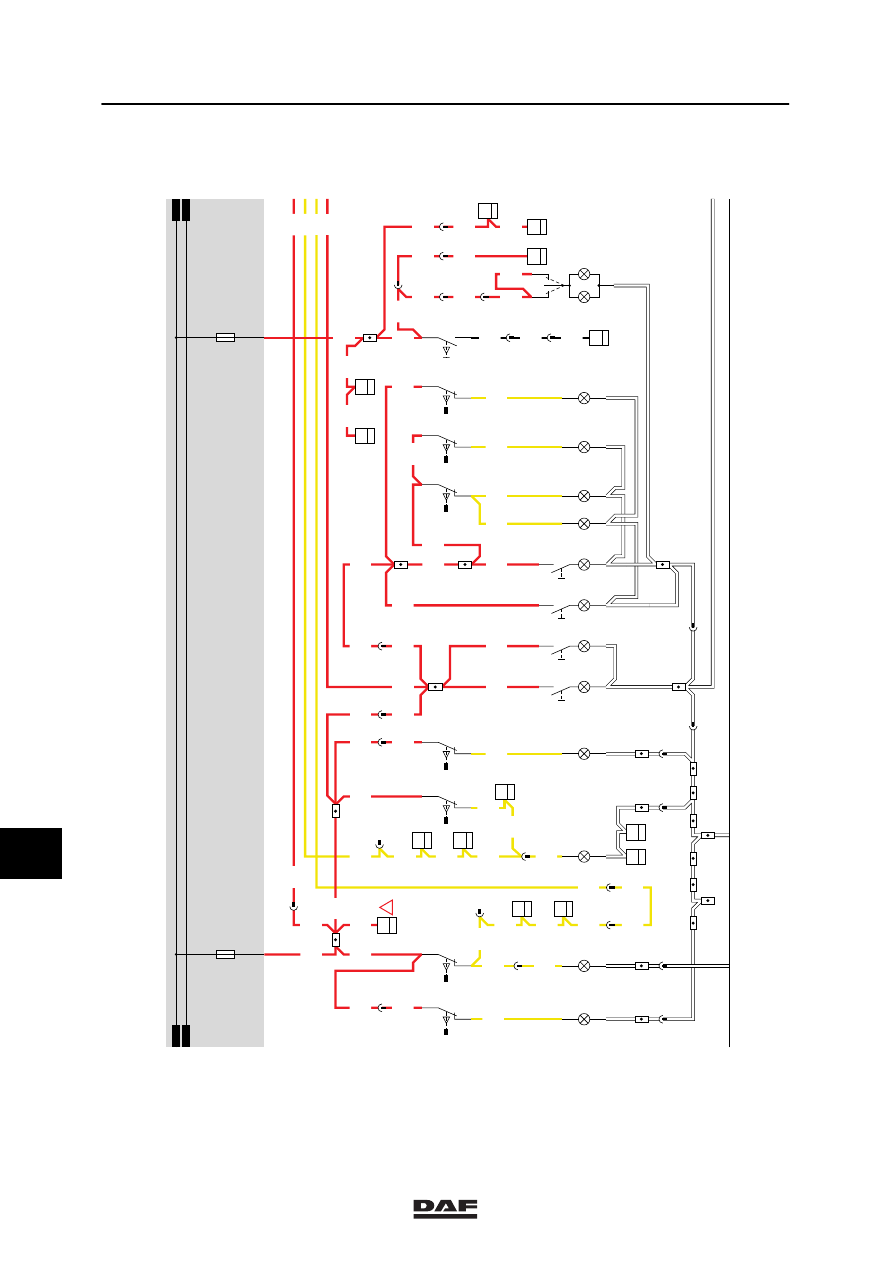
17. INTERIOR LIGHTING, SUPER SPACE CAB
The description of the interior lighting can be
divided into:
-
Stepwell lighting, driver’s side
-
Stepwell lighting, co-driver’s side
-
Interior lighting
-
Red interior nightlight
-
Interior bed lighting, driver’s side
-
Interior bed lighting, co-driver’s side
-
Bunk lamp
-
Storage compartment lighting
-
Map-reading lights
STEPWELL LIGHTING, DRIVER’S SIDE
If the driver’s side door is opened, switch E514
will close and the driver’s side stepwell lamp
(C062) will light up. A voltage is also applied
through wire 2600 to pin 17 of the CTE-2 unit
(D550). A voltage will be also be applied
internally to connection point 27 of CTE-2 unit
(D550), causing a lamp on the driver’s side
interior lighting (C149) to light up.
If the driver’s side door is closed, a voltage will
be applied to connection point 27 of the CTE
unit for approx. 9 sec. This will result in a delay
in switching off the interior lighting. If a speed
signal is applied to pin 18, the delayed switch-off
will not function. The stepwell lighting is
independent of the contact switch position.
STEPWELL LIGHTING, CO-DRIVER’S SIDE
If the co-driver’s side door is opened, switch
E515 will close and the co-driver’s side stepwell
lamp (C063) will light up. A voltage is also
applied to C148 (interior lighting, co-driver’s
side) through wire 2609, diode D708 and wire
2633.
INTERIOR LIGHTING UNDERSIDE ROOF
CONSOLE
A voltage is applied to switch C151 (interior
lighting with middle switch) through fuse E030
and wire 1104. Depending on the switch
position, C151 (interior lighting underside roof
console) will light up.
10
ǹ 9711
5
ELECTRICAL INSTALLATION
Electrical installation
2-80
RED INTERIOR NIGHTLIGHT
A voltage is applied to switch C735 (interior
nightlight switch) through fuse E028 and wire
1107. Depending on the switch position, C148
(interior nightlight, driver’s side) will light up.
INTERIOR LIGHTING, DRIVER’S SIDE
A voltage is applied to connection point 5 of
switch C733 (interior lighting roof console
driver’s side bed control) through fuse E028 and
wire 1107. If a connection is made in switch
C733 (contacts 5 and 7), a voltage will be
applied through wire 2644 and switch C734
(interior lighting roof console driver’s side central
console) (contacts 7 and 5) and wire 2632 to
both bulbs of C149.
A voltage is also applied to lamp C130 through
wire 2632.
INTERIOR BED LIGHTING, CO-DRIVER’S
SIDE
A voltage is applied to connection point 5 of
switch C731 (interior lighting roof console
co-driver’s side bed control) through fuse E028
and wire 1107. If a connection is made in switch
C731 (contacts 5 and 7), a voltage will be
applied through wire 2611 and switch C732
(interior lighting roof console co-driver’s side
central console) (contacts 7 and 5) and wire
2633 to bulb C148.
A voltage is also applied to lamp C139 through
wire 2633.
BUNK LAMP
The bunk light C115 can be switched on using a
switch.
The bunk lamp is independent of the contact
switch position.
STORAGE COMPARTMENT LIGHTING
A voltage is applied to switches E525 (central
upper storage compartment lighting switch),
E527 (right-hand storage compartment lighting
switch) and E560 (left-hand storage
compartment lighting switch) through fuse E028
and wire 1107. Door switches E525, E527 and
E560 are used to switch on/off lamps C064
(upper storage compartment lighting), C066
(right-hand storage compartment) and C150
(left-hand storage compartment) respectively.
10
ǹ 9711
5
Electrical installation
ELECTRICAL INSTALLATION
2-81
TOOLBOX LIGHTING
A voltage is applied to switches E528 (left-hand
toolbox lighting switch) and E529 (right-hand
toolbox lighting switch) through fuse E028 and
wire 1107. Switches E528 and E529 are used to
switch on/off lamps C067 and C068
respectively.
MAP-READING LIGHTS
A voltage is applied to the switches installed in
the map-reading lights on both the driver’s and
the co-driver’s side through fuse E208 and wire
1107. By pulling out the map-reading lights, the
switch is activated and the light is switched on.
VARIANTS
Location
9
This location is used to connect a voltage
converter for the radio memory. (The
voltage converter is an accessory!)
56 This connector is placed between the roof
upholstery and the roof. A PL lamp can be
connected to it. (The PL lamp is an
accessory!)
10
ǹ 9711
5
ELECTRICAL INSTALLATION
Electrical installation
2-82
1104
G297
B1
34
1107
24V
2
35
2600
2609
2609
17
1316630/05
EL000115
1107
2608
12
187
1107
2616
1107
18
286
2609
2609
21
185
2609
2609
D853
B5
7
2600
2600
2600
2600
2609
D862
3
36
2600
A040
4
42
2600
B001
2
39
B002
2
39
18
281
2605
2607
1107
2605
1107
1107
1107
2636
1107
1107
1107
1107
1107
1107
2600
2609
15/403
29/402
D862
4
36
2
185
C067
1
2
E528
2
1
E529
2
1
E514
2
1
C068
1
2
E515
2
1
C063
1
2
9
286
10
483
A040
5
42
8
189
C062
1
2
9
281
8
190
9
483
E525
2
1
1
2
E527
2
1
C066
1
2
C064
1
2
C047
2
1
C046
2
1
E560
2
1
C150
1
2
C110
2
1
C111
2
1
12
194
7
190
2
189
1107
1107
1107
2
190
1107
1107
1107
1107
1107
2609
2609
1107
C151
12
3
1104
1104
1
190
1104
1
189
1104
8
285
1104
1104
C736
1
36
C775
2
1
1104
1104
8
284
4535
4535
B028
1
22
3
281
4535
1
281
1104
1107
1107
2
187
1104
G297
B3
34
1
380
1104
1104
C736
8
36
1104
F616
1
36
D878
1010
1000
1010
1000
E028
15A
E030
10A
3
380
1107
1
23456789
1
0
1
1
1
2
1
3
1
4
1
5
1
6
1
7
1
8
1
9
2
0
2
1
2
2
2
3
2
4
2
5
2
6
2
7
2
8
2
9
3
0
3
1
3
2
3
3
3
4
3
5
3
6
3
7
3
8
3
9
4
0
4
1
4
2
4
3
4
4
4
5
4
6
4
7
4
8
4
9
5
0
5
1
5
2
5
3
!
1107
10
ǹ 9711
Нет комментариевНе стесняйтесь поделиться с нами вашим ценным мнением.
Текст