DAF 95XF. Manual — part 470
3
PNEUMATIC GEARBOX COMPONENTS
General
1-12
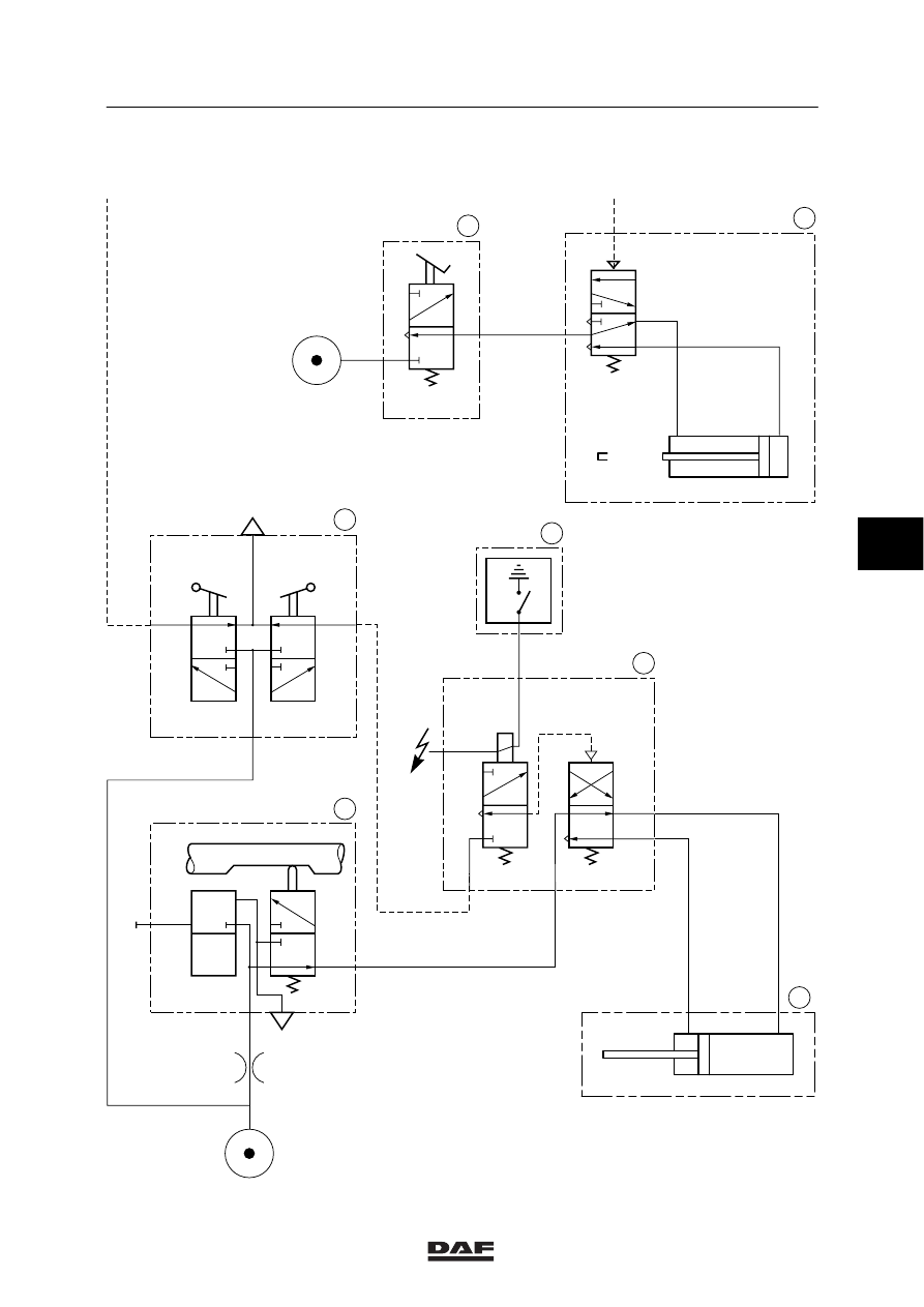
1.5 PNEUMATIC DIAGRAM OF THE GEARBOX CONTROL
Pneumatic diagram of 16 S direct input shaft
The following applies to pneumatic diagram
V300165
-
Vehicle contact switched off
-
Gearbox in neutral
-
Range switch position “high”
-
Splitter switch position “high”
-
Clutch pedal not activated
1.
Neutral position valve
2.
Gear engaging cylinder high/low group
3.
Shift-down safety valve
4.
Electronic unit for CTE
5.
Gear lever shifting valve
6.
GV valve
8.
Splitter relay valve with splitter cylinder
L
Position “low”
H
Position “high”
N
Gearbox selector shaft in neutral
V
Gearbox selector shaft engaged
5
ǹ 0002
3
General
PNEUMATIC GEARBOX COMPONENTS
1-13
Pneumatic diagram of 16 S direct input shaft
N
V
1
21
22
1
22
21
GV
GP
H
L
H
L
1
2
H
L
4
1
21
22
26
H
L
25
V300165
1
5
4
3
8
6
2
L
H
1
41
H
L
5
ǹ 0002
3
PNEUMATIC GEARBOX COMPONENTS
General
1-14
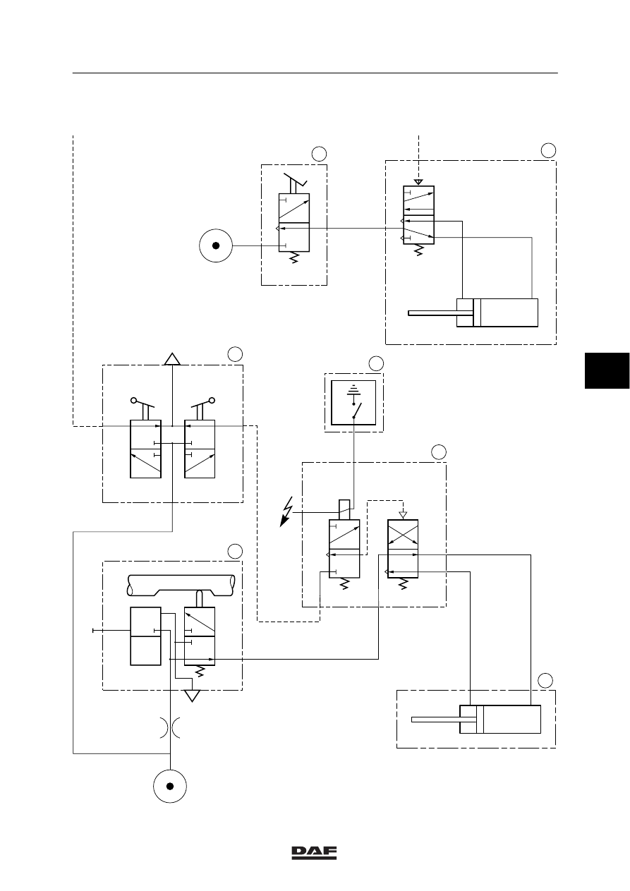
Pneumatic diagram of 16 S overdrive
The following applies to pneumatic diagram
V300166
-
Vehicle contact switched off
-
Gearbox in neutral
-
Range switch position “high”
-
Splitter switch position “high”
-
Clutch pedal not activated
1.
Neutral position valve
2.
Gear engaging cylinder high/low group
3.
Shift-down safety valve
4.
Electronic unit for CTE
5.
Gear lever shifting valve
6.
GV valve
7.
Splitter relay valve with splitter cylinder
L
Position “low”
H
Position “high”
N
Gearbox selector shaft in neutral
V
Gearbox selector shaft engaged
5
ǹ 0002
3
General
PNEUMATIC GEARBOX COMPONENTS
1-15
Pneumatic diagram of 16 S overdrive
N
V
1
21
22
1
22
21
GV
GP
H
L
H
L
L
H
1
41
H
L
1
2
H
L
4
1
21
22
V300166
1
5
4
3
7
6
26
H
L
25
2
5
ǹ 0002
Нет комментариевНе стесняйтесь поделиться с нами вашим ценным мнением.
Текст