DAF 95XF. Manual — part 299
5
Electrical installation
ELECTRICAL INSTALLATION
2-95
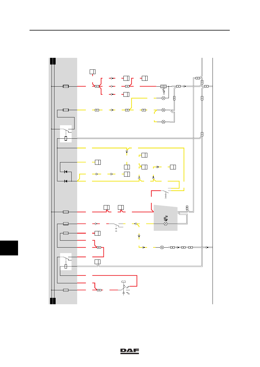
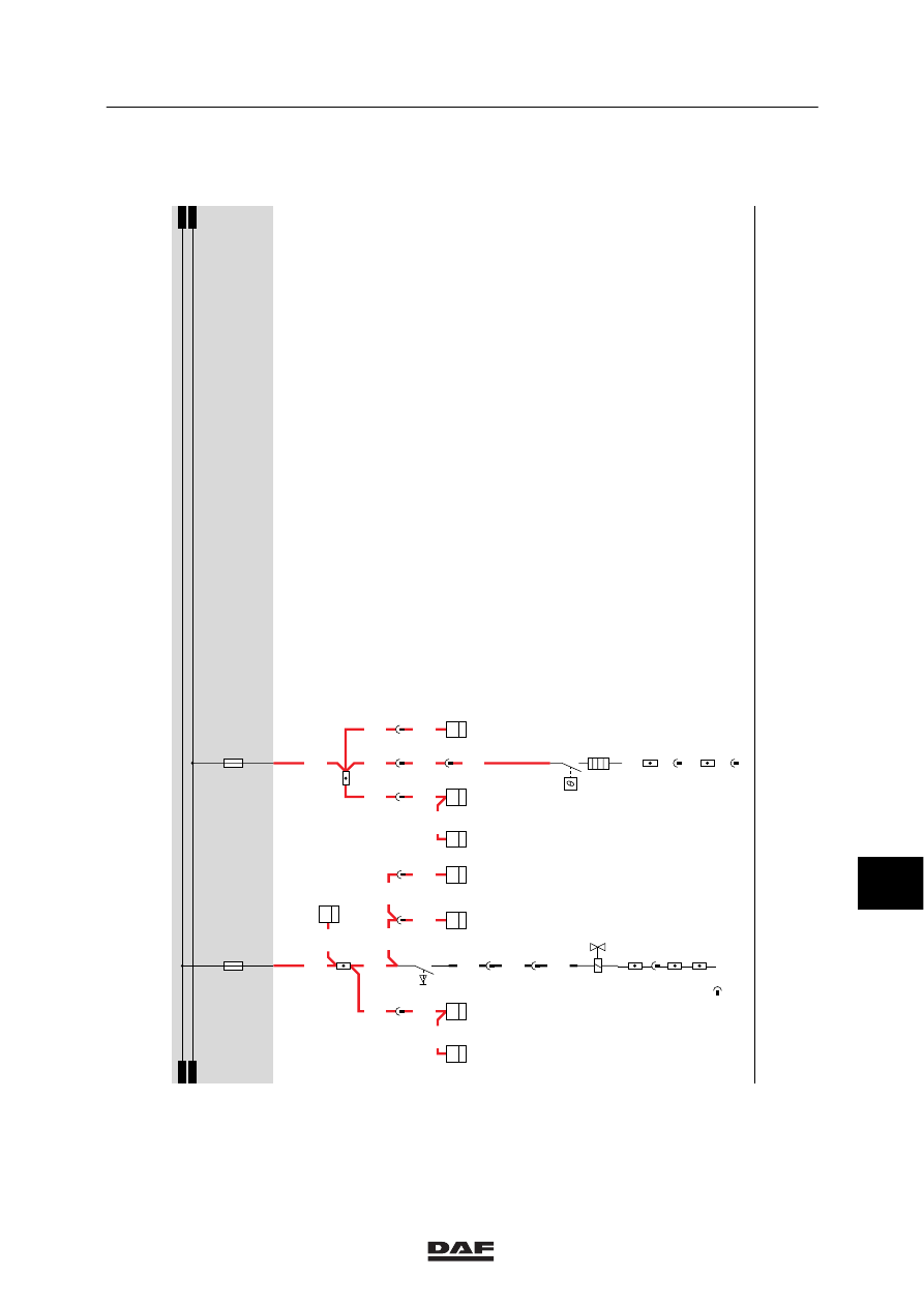
22. SIGNAL HORN / CIGARETTE LIGHTER / WORK LIGHT / AIR DRYER
SIGNAL HORN
The signal horn on this vehicle is a so-called
electropneumatic signal horn.
It consists of an electrically controlled air valve
and a diaphragm.
If the signal horn is engaged by activating switch
C775 (connection between contacts 8 and 9), a
voltage will be applied to the air-horn valve
(B028) through fuse E030, wire 1104, switch
C775 and wire 4535. The air horn will
subsequently be activated.
CIGARETTE LIGHTER
If heating element B030 of the cigarette lighter is
activated, the heating element in the cigarette
lighter is heated. When the switch heating
(C622) is activated, both the ashtray lighting
(C072) and the rim around the cigarette lighter
will light up.
WORK LIGHT
If the contact is positioned in or past the
accessory position, the work light (C071) can be
lit using switch C725. The light is fed through
fuse E307 and accessory relay (G178). This
relay is activated, after which the voltage is
applied to both the work-light switch (C725) and
the work light (C071) through fuse E052
(work-light fuse). At the same time a warning
lamp on the DIP is also activated.
AIR DRYER
If the contact relay (G015) is activated, a
voltage will be applied to connection point 1 of
air dryer B042 through fuse E091 and wire
1240. Pin 4 is connected to earth. Depending on
the temperature, the air dryer heating element is
switched on or off.
10
ǹ 9711
5
ELECTRICAL INSTALLATION
Electrical installation
2-96
22
1101
14/403
28/401
22/401
5/401
2154
C775
7
10
G003
86
10
2/231
1/231
4/231
1316630/05
EL000123
D853 B15
7
1101
1101
24/401
2110
B130
3
33
2110
4
286
2110
2110
4
288
C775
4
10
2110
5
176
4
281
2110
C773
5
11
2110
C764
5
33
2110
B129
3
33
2110
3
284
2110
2100
2100
C727
2
11
2100
4
176
2100
35/402
C622
0II
I
27/400
2630
15/402
19/402
1/412
2/412
4/412
6/412
34/400
1100
C539
20/402
1130
D525
2
35
1106
12/403
1110
3/402
32/400
1/402
1
176
1110
10/403
1147
1147
1147
1100
1100
C725
5
71
0I
2155
8
176
2155
1
493
2155
C071
1
2
11
493
D
115
29
115
2155
5/202
4/202
2155
2/239
10/201
D852
1101
2630
12
380
2630
2630
C072
1
2
2630
C073
1
2
2630
1181
1181
1
196
1181
1181
B199
1
36
1
276
1181
1181
D862
10
36
2
380
1181
A042
1
42
1181
1181
1181
B200
1
36
B030
2
1
31
2630
21
380
D878
1010
1000
1010
1000
2100
E084
10A
D609
D610
2154
30
86
85
87A
87
G000
M
2101
E182
15A
E117
10A
E037
15A
30
86
85
87A
87
G178
1100
1147
1130
E027
10A
E052
10A
1147
1
23456789
1
0
1
1
1
2
1
3
1
4
1
5
1
6
1
7
1
8
1
9
2
0
2
1
2
2
2
3
2
4
2
5
2
6
2
7
2
8
2
9
3
0
3
1
3
2
3
3
3
4
3
5
3
6
3
7
3
8
3
9
4
0
4
1
4
2
4
3
4
4
4
5
4
6
4
7
4
8
4
9
5
0
5
1
5
2
5
3
10
ǹ 9711
5
Electrical installation
ELECTRICAL INSTALLATION
2-97
1240
A043
1
42
1240
1240
B032
1
21
1240
1240
B033
1
21
1104
C151
1
16
1104
22
1316630/05
EL000124
18
286
29/402
1104
1104
1104
1104
G297
B3
34
1104
1104
C736
1
36
C736
8
36
13
281
4535
4535
8
284
4535
12
284
18
281
1104
F616
1
14
1104
25/400
1240
1240
1240
1240
12
288
D878
1010
1000
1010
1000
E030
10A
E091
15A
54
55
56
57
58
59
60
61
62
63
64
65
66
67
68
69
70
71
72
73
74
75
76
77
78
79
80
81
82
83
84
85
86
87
88
89
90
91
92
93
94
96
96
97
98
99
100
101
102
103
104
105
106
2
1
B028
B042
2
1
7
185
4
187
1
189
1
380
C775
9
8
1
281
1
286
1
288
10
ǹ 9711
5
ELECTRICAL INSTALLATION
Electrical installation
2-98
23. ABS / ASC
VARIANTS
Location
24 Connector A004 is only used in the case of
an FA. Connector A005 is used in the case
of an FT.
70 Connector 182 may not be connected. This
depends on whether or not an E-gas
system (D591) is installed.
SEE THE SYSTEM MANUAL FOR MORE
INFORMATION
10
ǹ 9711
Нет комментариевНе стесняйтесь поделиться с нами вашим ценным мнением.
Текст