DAF 95XF. Manual — part 298
5
Electrical installation
ELECTRICAL INSTALLATION
2-91
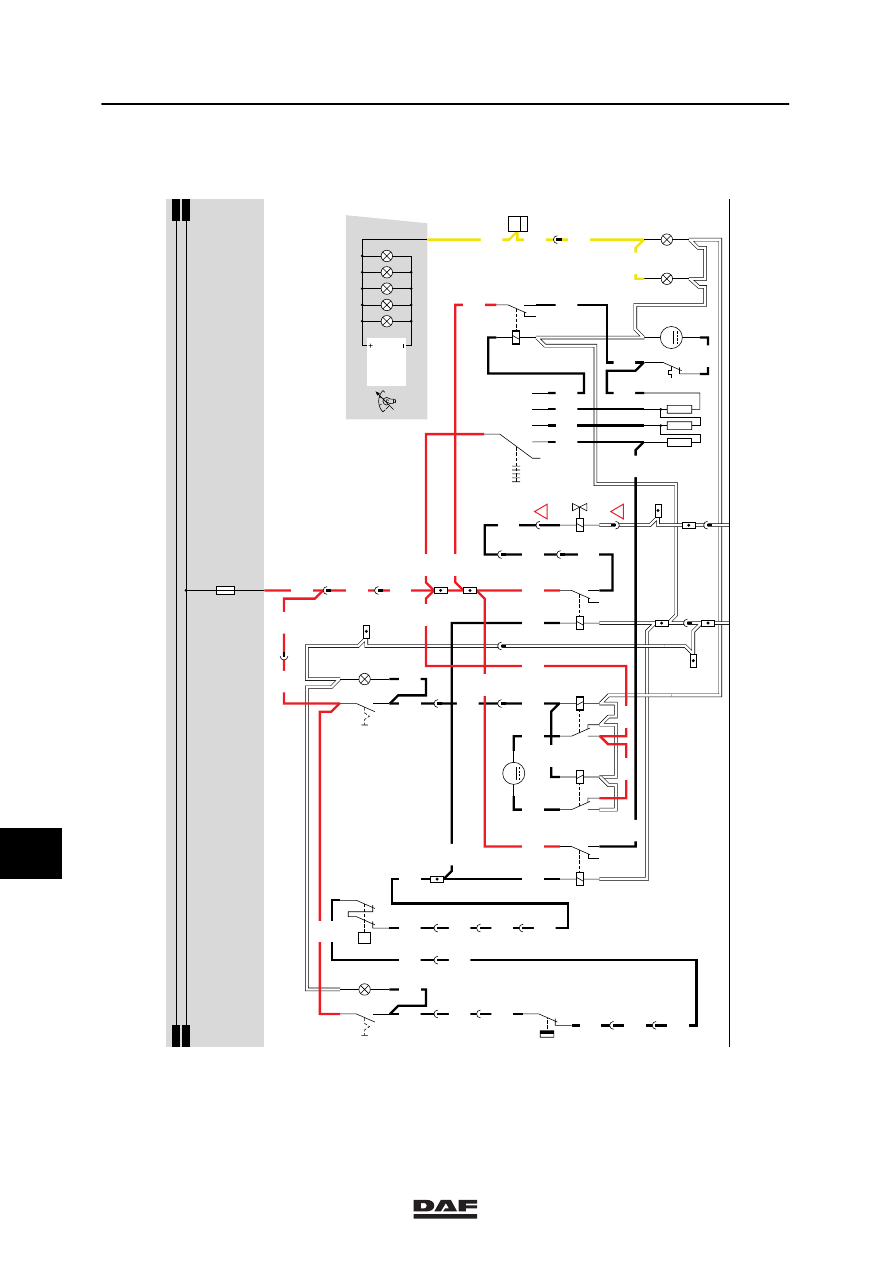
SHORT DESCRIPTION OF THE AIR-CONDITIONING SYSTEM
When the air-conditioning system is engaged
with switch C760, a voltage is applied to both
relay G279 and G267 through wire 4655, switch
E508 (air-conditioning compressor temperature
switch), E509 (air-conditioning high/low pressure
operating switch) and wire 4657.
As a result, the heater fan (B015) will start
operating in position 1 and the air-conditioning is
activated.
VARIANTS
Location
33 A round 4-pin black connector is attached
to the wiring harness coming from B043
(air-conditioning compressor). This
connector is not provided with a connector
number and is installed at the front (upper
centre) of the engine block.
SEE THE SYSTEM MANUAL FOR MORE
INFORMATION
10
ǹ 9711
5
ELECTRICAL INSTALLATION
Electrical installation
2-92
4655
C760
3
2
4
5
4655
4655
3
397
4655
20
1316630/05
EL000121
1201
1201
2622
B501
2
2
16/202
2622
2
397
2622
4650
4651
4652
4654
4654
4658
4653
4654
4650
4659
1
23456789
1
0
1
1
1
2
1
3
1
4
1
5
1
6
1
7
1
8
1
9
2
0
2
1
2
2
2
3
2
4
2
5
2
6
2
7
2
8
2
9
3
0
3
1
3
2
3
3
3
4
3
5
3
6
3
7
3
8
3
9
4
0
4
1
4
2
4
3
4
4
4
5
4
6
4
7
4
8
4
9
5
0
5
1
5
2
5
3
C053
1
2
C052
1
2
C588
1
4
5
3
2
6
5
3
2
14
B015
M
8
7
E508
3
1
E509
1
2
P
G280
30
86
85
87A
87
2622
1
397
1201
DVB
1201
C802
3
2
4
5
4659
17
376
4659
9
397
4659
1201
1
376
1201
4656
4
397
4656
2
175
4656
4656
16
376
15/401
4657
G279
3
1
24
5
2
1
B043
G267
3
1
24
5
4657
D852
1201
1201
4659
1201
B252
M
1
2
5054
5053
3
54
G257
1
2
3
54
G258
1
2
4657
3
175
2
183
4657
4657
5
397
4657
1201
4657
1201
1201
1201
4657
4650
12
397
1201
5055
14
114
8
397
5055
5055
1201
1201
D
114
4656
1
183
4656
!
!
21
376
D878
1010
1000
1010
1000
E031
15A
10
ǹ 9711
5
Electrical installation
ELECTRICAL INSTALLATION
2-93
21. SEAT HEATING / MICROWAVE
SEAT HEATING
If the vehicle is switched to contact, a voltage is
applied through fuse (E091) (wire 1240) to
switch C697 and C698. Depending on the
temperature, the thermostat switch in the seat
closes and the heating elements start glowing.
MICROWAVE
A wire which leads to the 40A fuse is connected
to connection 1000 of the Pertinax block in the
central fuse box. The other side of this fuse is
connected to a connector leading to the
overhead-box. The microwave can be
connected to it.
VARIANTS
Location
18 In an XL cab, connector 180 is installed
under the central fuse cabinet. The cable
harness (wire 1175 and earth) to the
overhead box is not installed. For the XH
and XC versions these wires are located in
the central overhead box.
ǹ 9711
10

5
ELECTRICAL INSTALLATION
Electrical installation
2-94
1316630/05
EL000122
21
25/400
1240
7
185
4
187
1240
1240
1240
1
286
1240
1240
1240
1
288
1240
B042
1
22
1240
A043
21
2
1
B033
2
1
B032
A
114
1000
1000
1010
1000
2/233
1/233
G525
G525
G014
1
3
1000
1000
1010
1000
1000
B
114
1000
1000
1000
1000
2
180
E168
40A
1175
A2
1
180
30
87
G015
1000
A500
1175
1000
A1
D878
E091
15A
1000
1010
1010
1000
1
23456789
1
0
1
1
1
2
1
3
1
4
1
5
1
6
1
7
1
8
1
9
2
0
2
1
2
2
2
3
2
4
2
5
2
6
2
7
2
8
2
9
3
0
3
1
3
2
3
3
3
4
3
5
3
6
3
7
3
8
3
9
4
0
4
1
4
2
4
3
4
4
4
5
4
6
4
7
4
8
4
9
5
0
5
1
5
2
5
3
50
B010
M
31
30
G
3
D
B+
D+
A502
A038
12
C698
2
13
C697
2
13
12
187
21
185
!
10
ǹ 9711
Нет комментариевНе стесняйтесь поделиться с нами вашим ценным мнением.
Текст