DAF 95XF. Manual — part 208
©
200438
2-1
ECAS-3 customer parameters
ECAS-3
DAVIE XD diagnostics manual
13
2. ECAS-3 CUSTOMER PARAMETERS
2.1 INTRODUCTION
Customer parameters
Customer parameters are the settings of an
electronic system. The customer parameters
permit adapting control functions of a system to
the customer's particular wishes and/or needs
within certain limits. The customer parameters
are stored in a list in the memory of the electronic
unit. Customer parameters can be modified using
the programming feature of DAVIE XD.
Programming using DAVIE XD is only possible if
the logged-in user has been registered as a
"Master Technician".
Note:
Erroneous settings of customer parameters may
affect the action of control functions to such an
extent that they function eratically or not at all.
After modification of the settings the (modified)
customer parameters must be stored in the
electronic unit using the programming function in
the customer parameter overview.
Customer parameter names and codes
Each customer parameter in a system has its
own name and code. The following explanation of
the customer parameters includes only the
codes. The availability of a customer parameter
in a system depends on the programmed
software in the electronic unit. The programmed
software depends on the vehicle configuration/
identity card data.
Standard values
Standard values, options and setting ranges may
vary according to the software variants of
DAVIE XD and the system. This is why they have
not been included in the following explanation of
the customer parameters.
ECAS-3
2-2
©
200438
ECAS-3 customer parameters
DAVIE XD diagnostics manual
13
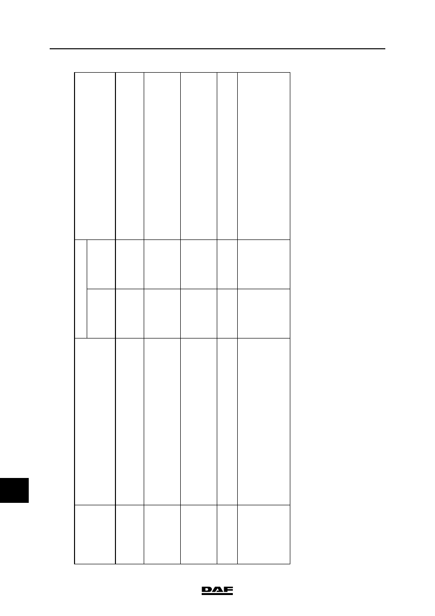
2.2
E
X
P
LANATORY
NOTES
TO ECAS-3
CUSTOME
R
PARAME
TERS
ECAS
-3
c
u
sto
m
er
para
meter
c
o
de
Exp
la
n
atio
n
D
e
p
en
de
nc
es:
Notes
Minimum
va
lu
e to be
se
t:
Ma
ximum
value
to
b
e
set:
4
-0
1
Wi
th
thi
s
p
arameter the protection
fo
r e
m
p
ty be
llow
s ca
n
be
swi
tche
d on or off.
When
the
p
rote
cti
on is switched off, there is no resid
ual
pressure in the air be
llow
s so that
'p
leating
' of
the
bell
ows is
n
o long
er prevented
.
4
-0
2
T
his parameter makes it
po
ssible
to increa
se th
e
tolera
nce fi
eld (hysteresis)
of the
sen
sor se
nsitivity.
Thi
s
is a
solu
tion
if a
cu
sto
m
e
r compla
ins a
bou
t unstabl
e
re
gul
ati
on by ECAS-3. If a larg
er
tol
erance
fiel
d is
ch
osen, th
e heig
ht
cha
nge
o
f th
e chassis must be
increase
d to al
low ECAS
to make a correction.
4
-0
3
T
his parameter ena
ble
s a certain
veh
icle slan
t to be
redu
ced or increa
se
d.
Redu
ctio
n ma
kes
the
veh
icle stand stra
igh
te
r (if
the
ca
libra
tion is correct, i.e
. the
sa
me hei
ght left and ri
ght).
Incre
ase will
make the vehi
cle slant fu
rth
er, thereb
y
enab
ling
u
nstable
h
orizontal
setting
s
to
be
preve
nte
d.
4
-0
4
T
he time of th
e de
lay setti
ng can
be le
ngthe
ned w
ith
th
is
par
a
meter.
4
-0
5
T
his parameter rela
tes to
th
e
storag
e of
faul
ts in the
el
ectro
nic unit on the action of admitting ai
r to or
exha
usting
ai
r
from the
ai
r b
ello
ws.
A
fa
ult is i
den
tifie
d if the
hei
ght sen
sor read
ing
doe
s not
ch
ang
e d
uring
the
p
ro
grammed
time
whil
e i
t shou
ld
have do
ne becau
se of
the de
sired action
. Th
is
time can
be lengthened with this
pa
rameter. The
ECAS system
the
n waits long
er
b
efore sto
ring the fa
ult becau
se
the
heig
ht
sen
sor
re
adin
g has not ch
ang
ed.
©
200438
3-1
System inspection with DAVIE XD
ECAS-3
DAVIE XD diagnostics manual
13
3. SYSTEM INSPECTION WITH DAVIE XD
3.1 CALIBRATING THE SENSORS
The sensors must be calibrated if the height
sensors or the ECAS unit are replaced.
Note:
Calibration should be carried out with due care to
avoid physical injury and material damage.
When calibrating, the maximum desired chassis
height at the rear axle and the maximum desired
chassis height at the front axle must be
calibrated.
Notes to sensor calibration
1.
Place the gauges between the driven axle
and the chassis.
2.
Lower the chassis using DAVIE until it rests
on the gauges.
Note:
-
On vehicles with an air-sprung front axle
a gauge must also be placed between
the axle and the chassis.
3.
Now bring the chassis to the desired
maximum height at the front axle.
Then bring the chassis to the desired
maximum height at the rear axle.
Note:
The maximum height of the chassis is limited
by the mechanical stop of the shock
absorber.
The shock absorber of the non-driven axle
may reach its stop before the shock absorber
of the driven axle.
ECAS-3
3-2
©
200438
System inspection with DAVIE XD
13
DAVIE XD diagnostics manual
3.2 INSPECTION OF HEIGHT SENSORS
1.
Admit air to the bellows. The value indicated
by DAVIE must now show a linear increase.
2.
Exhaust air from the bellows. The value
indicated by DAVIE must now show a linear
decrease.
Note:
If two height sensors are used, these two
sensors, with the vehicle at the driving level, may
give a different reading (caused, for example, by
play in the linkage). This may result in the vehicle
not being level. This can be solved by
recalibrating the sensors.
Нет комментариевНе стесняйтесь поделиться с нами вашим ценным мнением.
Текст