DAF 95XF. Manual — part 130
6
Inspection and adjustment
BRAKE COMPONENTS
1-3
9.
Run the engine at idling speed.
10. Bleed the brake system until the governor
cut-in pressure is reached. The indicator on
the pressure gauge should not drop rapidly.
If necessary, check the system for leaks;
special attention should be paid to the
compressor line and the compressor.
11. Replace the safety valve.
12. Remove compressor control line which is
connected at port (23) of the air dryer.
4
ǹ 0006
6
BRAKE COMPONENTS
Inspection and adjustment
1-4
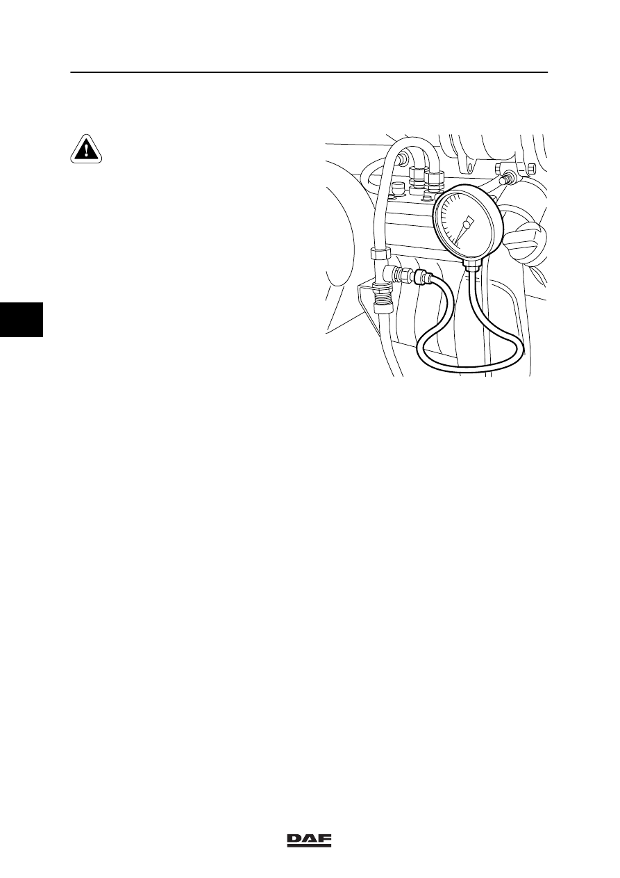
1.3 INSPECTION OF COMPRESSOR CONTROL
Maintain a safe distance from
rotating and/or moving
components.
1.
Run the engine to operating temperature.
2.
When the engine is not running, remove the
safety valve from the compressor line and
replace it with a test nipple.
3.
Connect a pressure gauge (measuring
range 0 - 16 bar) to the test nipple.
4.
Start the engine and run it at maximum
speed.
5.
The pressure gauge should indicate a
pressure of approx. 0 bar with the
pressure regulator switched off.
6.
Reassemble the safety valve from the
compressor line, when the engine is not
running.
R600249
4
ǹ 0006
6
Inspection and adjustment
BRAKE COMPONENTS
1-5
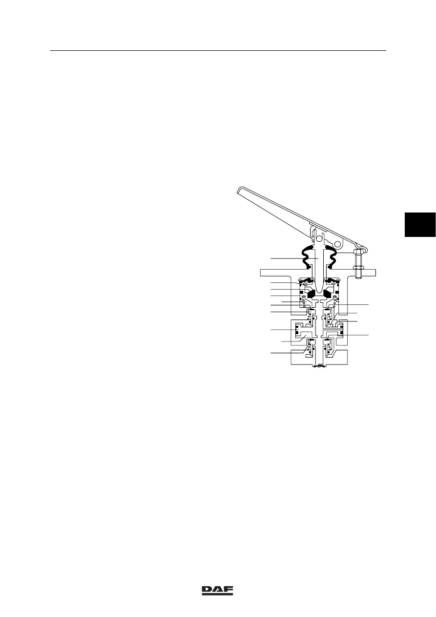
1.4 INSPECTION AND ADJUSTMENT, SERVICE-BRAKE VALVE
Inspection foot-brake valve
1.
Connect a pressure gauge to one brake
chamber of the front axle (if present, in front
of the empty/load valve).
2.
Connect a pressure gauge in front of the
load-sensing valve.
3.
Pressurise the system.
4.
Depress the brake pedal a few times,
alternately quickly and slowly, until the end
stop.
Check if there is a discrepancy between
both gauge readings (discrepancy
maximum 0.3 bar).
5.
When the brake pedal is gradually
depressed, both circuits should not show
larger pressure increases than 0.3 bar.
6.
When the service-brake valve is completely
depressed, the reading of both gauges
should indicate the reservoir pressure.
7.
When the brake pedal is not depressed, the
pressure gauges should not indicate any
pressure.
Adjusting the service-brake valve
1.
Check whether the brake pedal can be fully
depressed. When fully depressed, the pedal
should not touch the floor mat. This is
especially important if circuit 1 were to be
break down. The pedal will need to be
depressed more than once to achieve full
pressure at circuit 2.
2.
The stop bolt should be adjusted so, that
there is a noticeable play between bolt and
pedal.
21
22
12
A
B
D
C
10
9
7
8
6
5
4
3
2
1
11
W604033
Fig. 2
4
ǹ 0006
6
BRAKE COMPONENTS
Inspection and adjustment
1-6
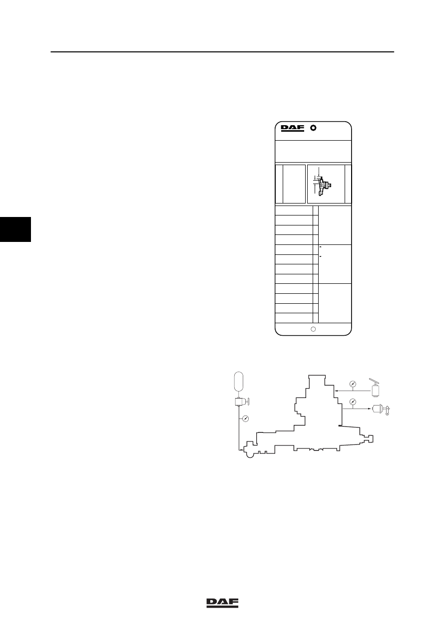
1.5 INSPECTION AND ADJUSTMENT, LOAD-SENSING VALVE, AIR
SUSPENSION
Explanation of instruction plate
The information contained on the instruction
plate relates to the axle loads, the output
pressures and bellows pressures, in accordance
with the order of axles beneath the vehicle.
So “1” is the front axle, etc.
The data for the “driven axle” given on the
instruction plate are important when the
load-sensing valve is checked.
L1 = Effective length of unloaded spring
between retainer sleeve and adjustable
plug. Spring length in mm.
L2 = Screw length up to lock nut in mm.
1.
Check whether the correct valve is fitted
(see instruction plate).
2.
Connect pressure gauge (4) to the test
connection of the load-sensing valve (input
pressure).
3.
Connect pressure gauge (2) to the test
connection at the rear-axle brake cylinder
(output pressure).
4.
Connect pressure gauge (43) with a
pressure-reducing valve to the simulation
connection of the load-sensing valve
(simulated adjustable bellows pressure).
5.
Make sure that the reservoir pressure is
higher than 6.5 bar throughout the testing
process.
MEEREGELVENTIEL
EMPTY-LOAD VALVE
LAST-LEER VENTIEL
VALVE CHARGE-VIDE
VALVOLA VUOTO-CARICO
VALVULA VIDA-CARGA
ASLAST
AXLE LOAD
ACHSLAST
CHARGE SOUS ESSIEU
CARICO ASSE
CARGA EJE
UITGESTUURDE DRUK
DELIVERY PRESSURE
AUSGESTEUERTER DRUCK
PRESSION DELIVREE
PRESSIONE USCITA
PRESION DE SALIDA
G
p
2
BALGDRUK
PRESSURE BELLOWS
BALG DRUCK
PRESSION COUSSIN
PRESS.CUSCINI ARIA
PRESION FUELLES
p3
bar
bar
x 10
4
N
AUTOM. LASTAFHANKELIJKE REMKRACHTREGELING
AUTOM. LOAD SENSING DEVICE
AUTOM LASTABHANGIGE BREMSKRAFT REGELINR.
DISPOSITIF DE CORRECTION AUTOM DE FREINAGE
REGOLATORE AUTOM. DELLA FORZA FRENANTE
REGULADOR AUTOM. DEL ESFUERZO DE FRENADA
1263639
TYPE - TIPO : FA
W 475 711 071 0
p1= > 6.5 bar
p4= 6.0 bar
L1 = 114.0 MM L2 = 4.0 MM
2
1
2.0
2.5
3.0
4.0
10.0
11.5
12.0
13.0
2
1
1.4
1.5
1.6
2.0
4.6
5.3
5.5
5.9
4.3
4.4
4.4
4.5
5.8
5.9
5.9
6.0
2
1
0.3
0.5
0.7
1.2
4.1
4.8
5.1
5.6
0.2
0.4
L2
p1
p4
p3
L1
i = 1: 1.5
M6046
42
1
2
4
2
4
41
43
M6102
4
ǹ 0006
Нет комментариевНе стесняйтесь поделиться с нами вашим ценным мнением.
Текст