DAF 95XF. Manual — part 239
5
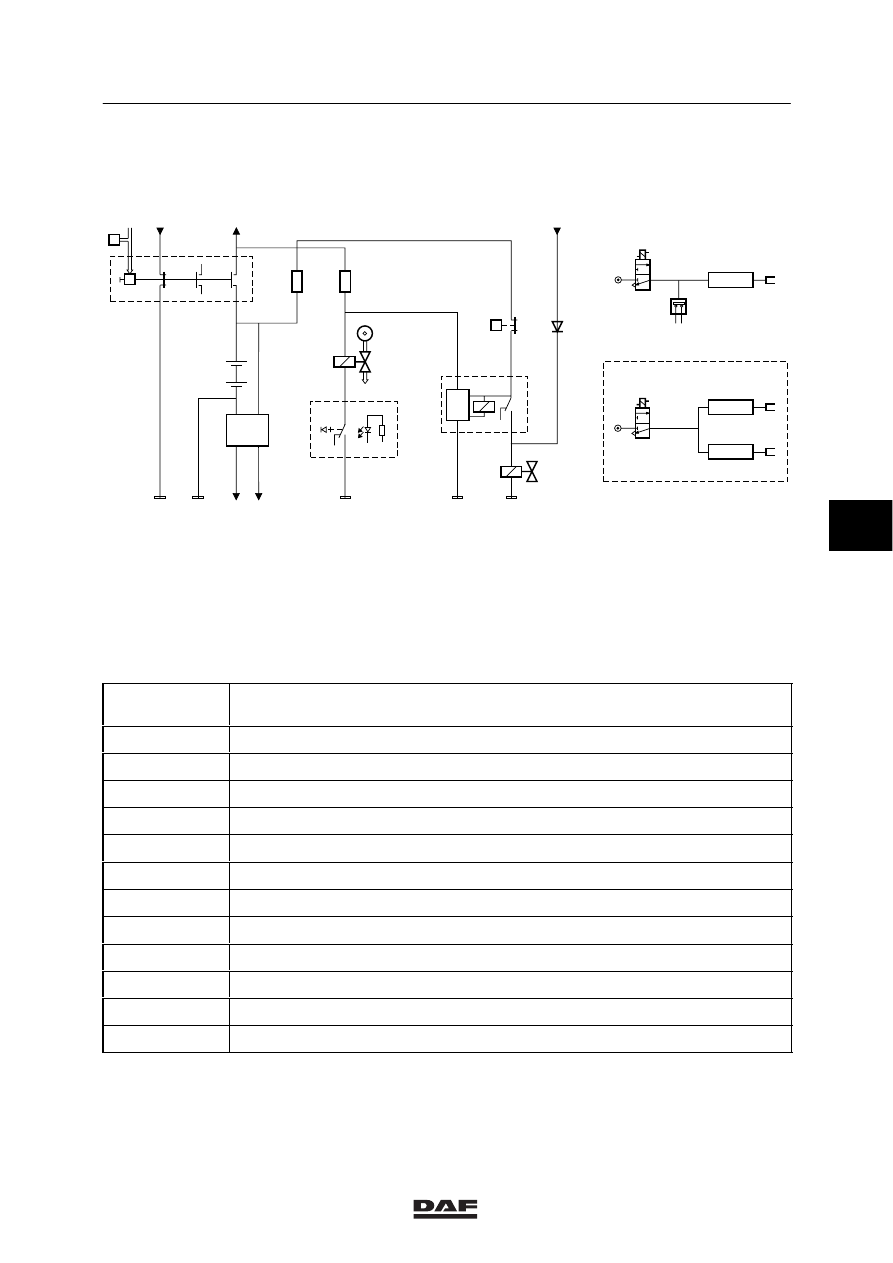
Master switch diagram
MASTER SWITCHES
1-3
1.3 ELECTRIC-CONTROL MASTER SWITCH FOR VLG/ADR/GGVS
P
P
P
1167
+
+
+
-
-
-
E500133
D701
E559
1166
E152
E153
1122
A500
4986
4049
4985
B082
B085
C555
C752
5
1
B A
7
l
0
5065
1020
D+
B085
E559
6
5
C555
9303
1123
24V
24V
D826
1
2
4
3
1000
G186
T=
60s
6
5
8
2
4
B501
A1:1123
A5:9303
1
2
3
B082
B
C
1
2
3
A
E559
B085
C555
0,5 bar
A:
Electropneumatic switch in cab
B:
Fuel pump
C:
Exhaust valve
Basic code
number
Designation
A500
Batteries (2)
B082
Engine stop/engine brake valve
B085
Master switch control valve
B501
Compact tachograph
C555
Pneumatic master switch
C752
Master switch control switch
D701
Master switch diode preventing feedback to CTE
D826
Electronic unit for current limiter VLG
E152
Fuse for master switch/ timer/ engine stop/ power supply after master switch
E153
Fuse for master switch/ timer/ engine stop/ power supply before master switch
E559
Control switch for pneumatic master switch/ engine stop break
G186
Timer relay for the engine stop master switch
5
ǹ 9711
5
MASTER SWITCHES
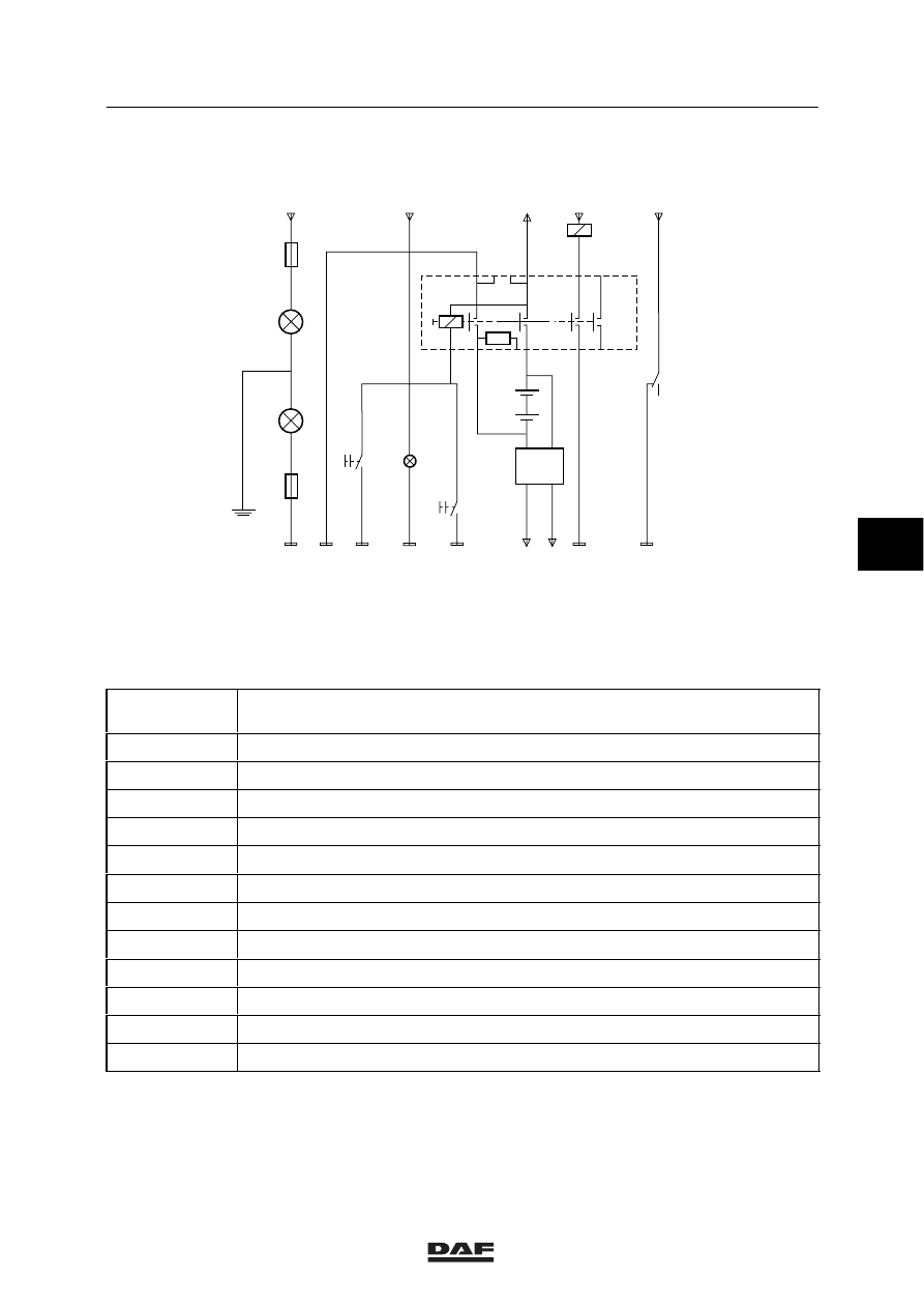
Master switch diagram
1-4
Master switch C555 should be switched on
manually outside the cab.
The master switch can be switched off:
-
Manually (outside the cab)
-
Pneumatically (inside the cab)
Relay G186 is activated when the voltage on pin
4 drops out. Engine stop valve B082 will then be
activated for 60 seconds.
If pressure switch E559 is open, engine stop
valve B082 is not activated.
Switch A can be used to switch off the master
switch pneumatically inside the cab. This also
involves the opening of pressure switch E559.
5
ǹ 9711
5
Master switch diagram
MASTER SWITCHES
1-5
1.4 ELECTRIC-CONTROL TWO-POLE MASTER SWITCH FOR PETREG
+
+
+
-
-
-
C622
1000
1000
3600
E154
E500134
C667
C668
9300
9303
1123
24V
1127
5
1
6
3
G056
30
A
1122
8
12
4
10
1024
9505
C669
D110
D111
E155
12V
A500
G056
D545
1020
87A
B520
A1:1123
A5:9303
3601
2630
9504
4985
2
9
11 7
D+
B
A:
Special reference earth on chassis
B:
Electric earth insulated (i.e. not on chassis)
Basic code
number
Designation
A500
Batteries (2)
B520
Compact tachograph (12V)
C622
Lighting switch
C667
Electric master switch cut-out switch (cab)
C668
Electric master switch cut-out switch (chassis)
C669
Switch for electric master switch
D110
Indicator lamp for master switch leakage current to power supply
D111
Indicator lamp for master switch leakage current to earth
D545
Electronic unit current limiter converter 12/24V
E154
Fuse for master switch leakage current to power supply
E155
Fuse for master switch leakage current to earth
G056
Master switch control relay
5
ǹ 9711
5
MASTER SWITCHES
Master switch diagram
1-6
The electric master switch C669 must be
switched on manually outside the cab.
The electric master switch can be switched off in
the following ways:
-
Manually (outside the cab)
-
Electrically (outside the cab)
-
Electrically (inside the cab)
When switch C667 or C668 is closed, the relay
of the electric master switch is activated, so that
the electric master switch is switched off.
As soon as the electric master switch is
switched off there will be no voltage on the relay.
When the electric master switch is switched off,
the engine continues to operate.
D+ will then be connected to earth.
5
ǹ 9711
Нет комментариевНе стесняйтесь поделиться с нами вашим ценным мнением.
Текст