DAF 95XF. Manual — part 240
5
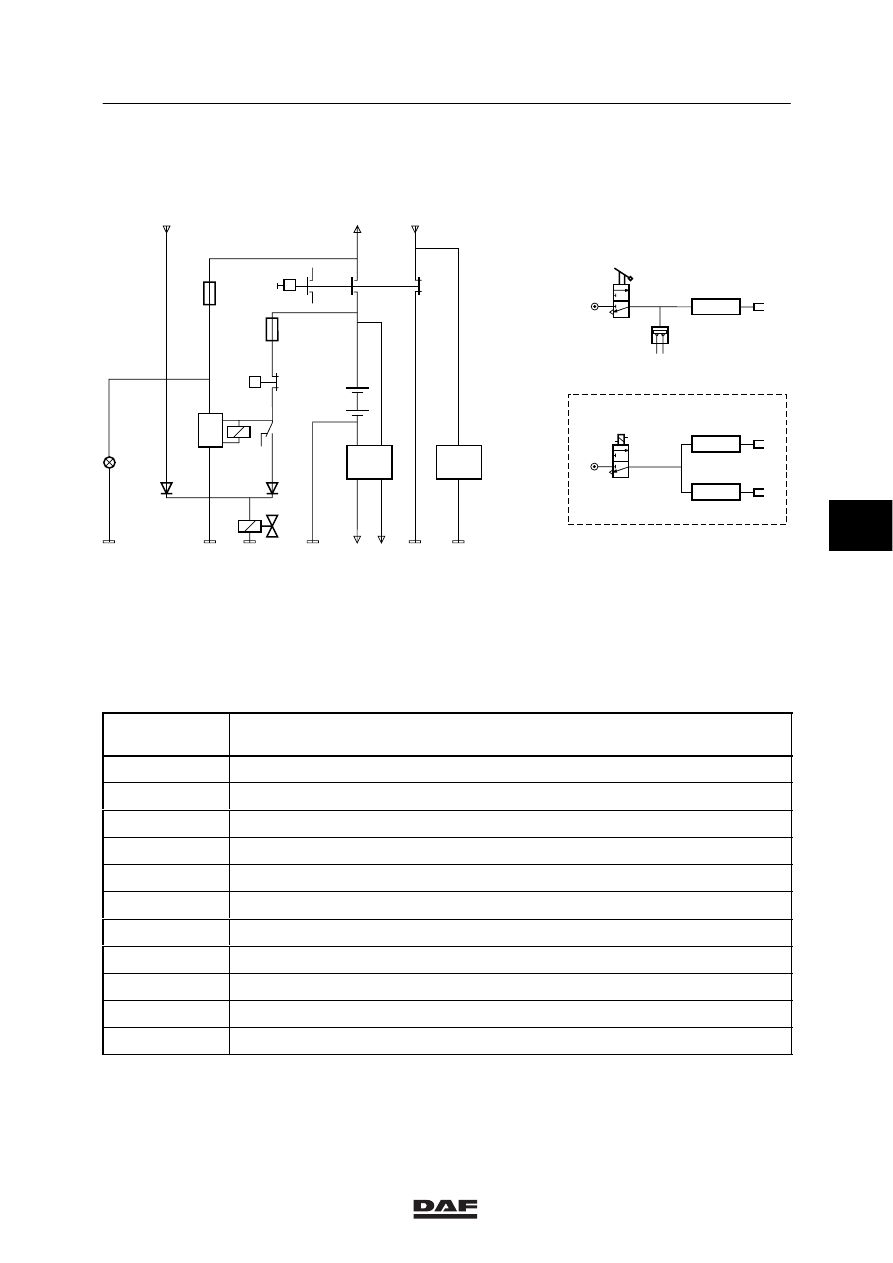
Master switch diagram
MASTER SWITCHES
1-7
1.5 PNEUMATIC-CONTROL SINGLE-POLE MASTER SWITCH FOR
VLG/ADR/GGVS
D+
+
+
+
-
-
+
-
-
9303
1123
24V
1122
24V
D826
D552
P
P
4049/4683
1166
4986
4984
D701
D702
B082
E559
A500
6
5
1
2
4
3
1020
D550/G146
1000
E500130
1167
4985
G186
E153
C555
E152
D018
T=
60s
6
5
8
2
4
B501
A1:1123
A5:9303
1
2
3
B082
B
C
1
2
3
A
E559
C555
0,5 bar
A:
Pneumatic switch in cab
B:
Fuel pump
C:
Exhaust valve
Basic code
number
Designation
A500
Batteries (2)
B082
Engine stop valve
B501
Compact tachograph
C555
Pneumatic master switch
D018
Master switch indicator lamp
D701
Master switch diode preventing feedback to CTE
D702
Master switch diode preventing feedback to engine stop relay
D550
Electronic unit for central timing unit (2nd)
D552
Generator overvoltage protection
D826
Electronic unit for current limiter VLG
E152
Fuse for master switch/ timer/ engine stop/ power supply after master switch
5
ǹ 9711
5
MASTER SWITCHES
Master switch diagram
1-8
Basic code
number
Designation
E153
Fuse for master switch/ timer/ engine stop/ power supply before master switch
E559
Control switch for pneumatic master switch, engine stop break
G146
Timer relay for electric engine stop
G186
Timer relay for the master switch
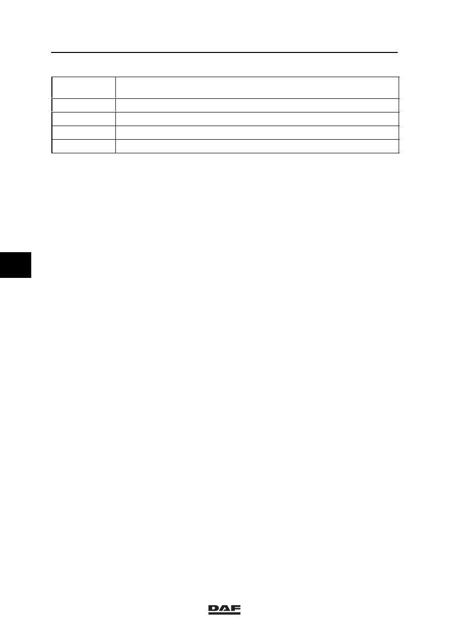
Master switch C555 should be switched on
manually outside the cab.
The master switch can be switched off in the
following ways:
-
Manually (outside the cab)
-
Pneumatically (inside the cab)
Relay G186 is activated when the voltage on pin
4 drops out. Engine stop valve B082 will then be
activated for 60 seconds.
If pressure switch E559 is open, engine stop
valve B082 is not activated.
Switch A can be used to switch off the master
switch pneumatically inside the cab. This also
involves the opening of pressure switch E559.
5
ǹ 9711
5
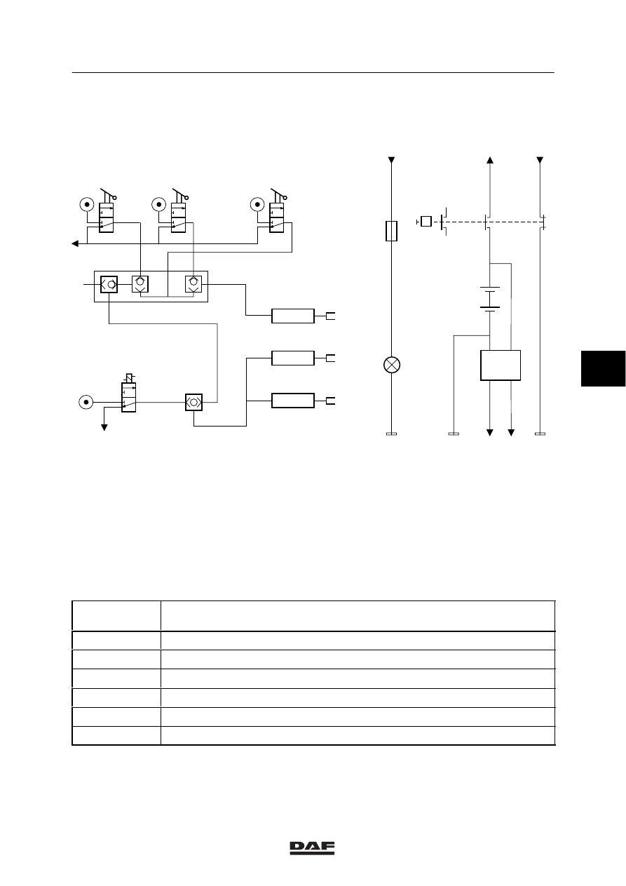
Master switch diagram
MASTER SWITCHES
1-9
1.6 PNEUMATIC-CONTROL SINGLE-POLE MASTER SWITCH FOR RTMDR
E500132
1
2
B
D
F
E
A
C
2
12
11
3
B082
G
H
J
+
+
+
-
-
-
D018
A500
1122
1020
6
5
9303
4698
1123
24V
D826
4
D+
1000
1000
3
B501
A1:1123
A5:9303
P
C555
2
1
E092
1
2
3
M
1
2
3
L
K
1
2
3
A
= Connection to collection block
B
= See A
C
= See A
D
= See A
E
= See A
F
= See A
G
= Fuel pump
H
= Exhaust valve
J
= Master switch
K
= Engine stop
L
= Master switch
M
= Engine stop + master switch
Basic code
number
Designation
A500
Batteries (2)
B501
Compact tachograph
C555
Pneumatic master switch
D018
Green master switch indicator lamp
D826
Electronic unit for current limiter VLG
E092
Fuse for master switch valve
5
ǹ 9711
5
MASTER SWITCHES
Master switch diagram
1-10
Master switch C555 should be switched on
manually outside the cab.
The master switch can be switched off in the
following ways:
-
Manually (outside the cab)
-
Pneumatically (inside the cab)
5
ǹ 9711
Нет комментариевНе стесняйтесь поделиться с нами вашим ценным мнением.
Текст