DAF 95XF. Manual — part 244
5
Connecting accessories
CONNECTING ACCESSORIES
1-11
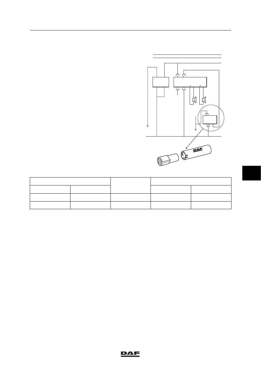
CHANNEL MEMORY OF RADIO IN COMBINATION WITH 24/12V 4A CONVERTER
Channel memory of Philips radio
For the channel memory it is necessary to link
connection point 4 of the radio connector to the
12V supply voltage before contact, using an
electronic unit for the power supply of the radio
memory (D828).
L
R+
L+
R
4542
4540
4543
4541
12V
12V
6
12V
7
B024
B025
B023
D525
D828
2
4
1
3
12V
24V
8
4
1000
1010
1108
4
24V
12V
2
M
1
106
1
107
E500728
1295795
Note:
Input
Voltage before/
Output
24 V
Wire no.
Voltage before/
after the contact
12 V
Wire no.
2
1106
after
4
1108
2
1107
before
6
ǹ 0009
5
CONNECTING ACCESSORIES
Connecting accessories
1-12
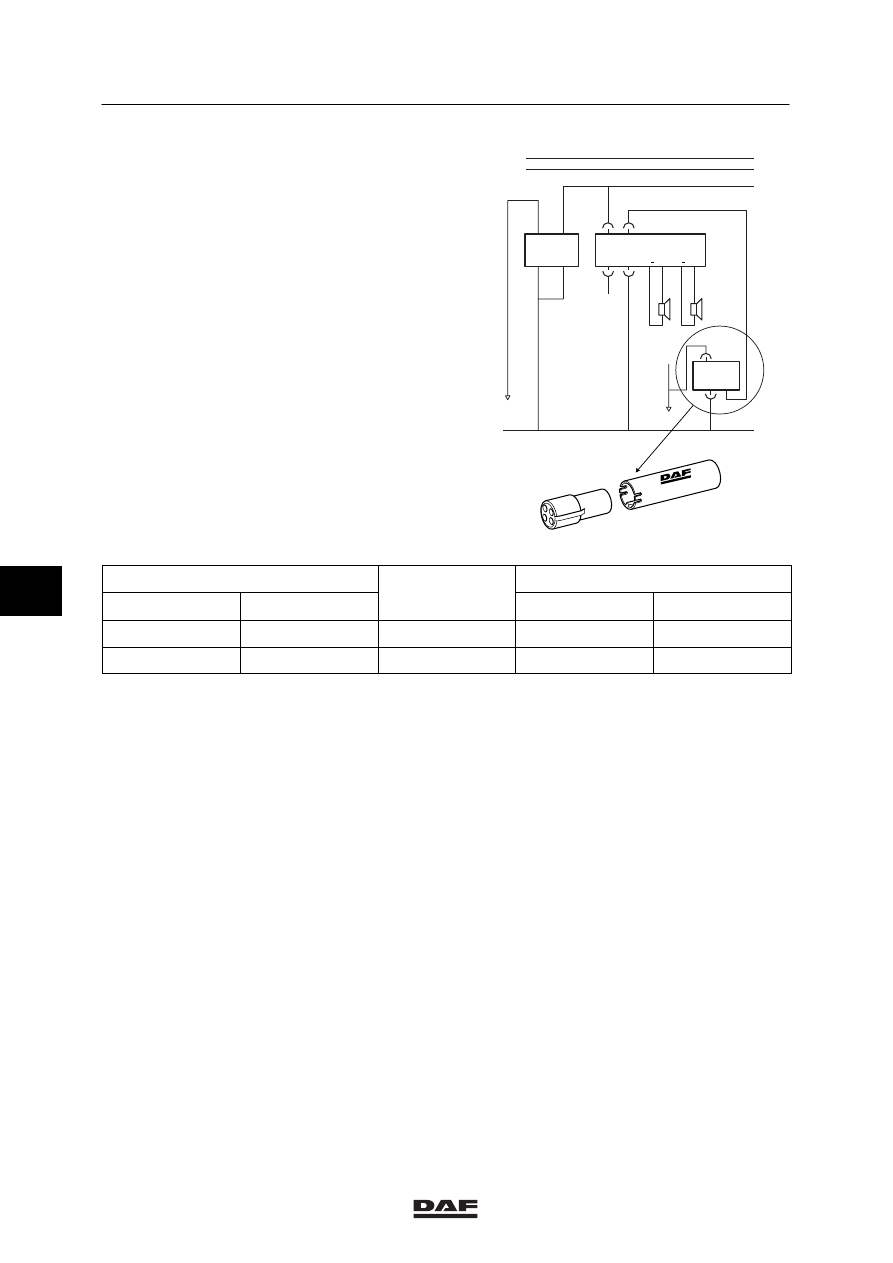
Channel memory of Grundig radio
For the channel memory it is necessary to link
connection point 7 of the radio connector to the
12V supply voltage after contact, using an
electronic unit for the power supply of the radio
memory (D828).
Note:
Wire 1106 is for the 24V supply voltage,
connected in contact/starter switch position with
relay G178: “accessories”.
L
R+
L+
R
4542
4540
4543
4541
12V
12V
6
12V
4
B024
B025
B023
D525
D828
2
4
1
3
12V
24V
8
7
1000
1010
1108
4
24V
12V
2
M
1
107
1
106
E500729
1295795
Input
Voltage before/
Output
24 V
Wire no.
Voltage before/
after the contact
12 V
Wire no.
2
1106
after
2
1107
before
4
1108
6
ǹ 0009
5
Connecting accessories
CONNECTING ACCESSORIES
1-13
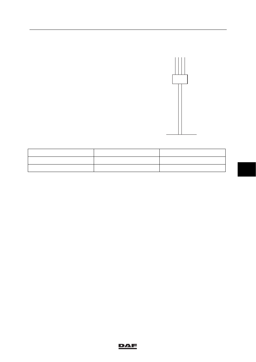
CHANNEL MEMORY OF RADIO IN COMBINATION WITH 24/12V 10A OR 20A
CONVERTER
Two variants of this converter are available:
24V/12V (10A + 10mA) or:
24V/12V (20A + 10mA)
Both are connected in the same way.
The converter has two individual in- and outputs:
D895
12V
24V
B1
A4
B2
A3
A1
A2
M
E500726
24V input
12V output
Max. amperage
A2
A4
10 or 20A
B2
B1
10 mA
6
ǹ 0009
5
CONNECTING ACCESSORIES
Connecting accessories
1-14
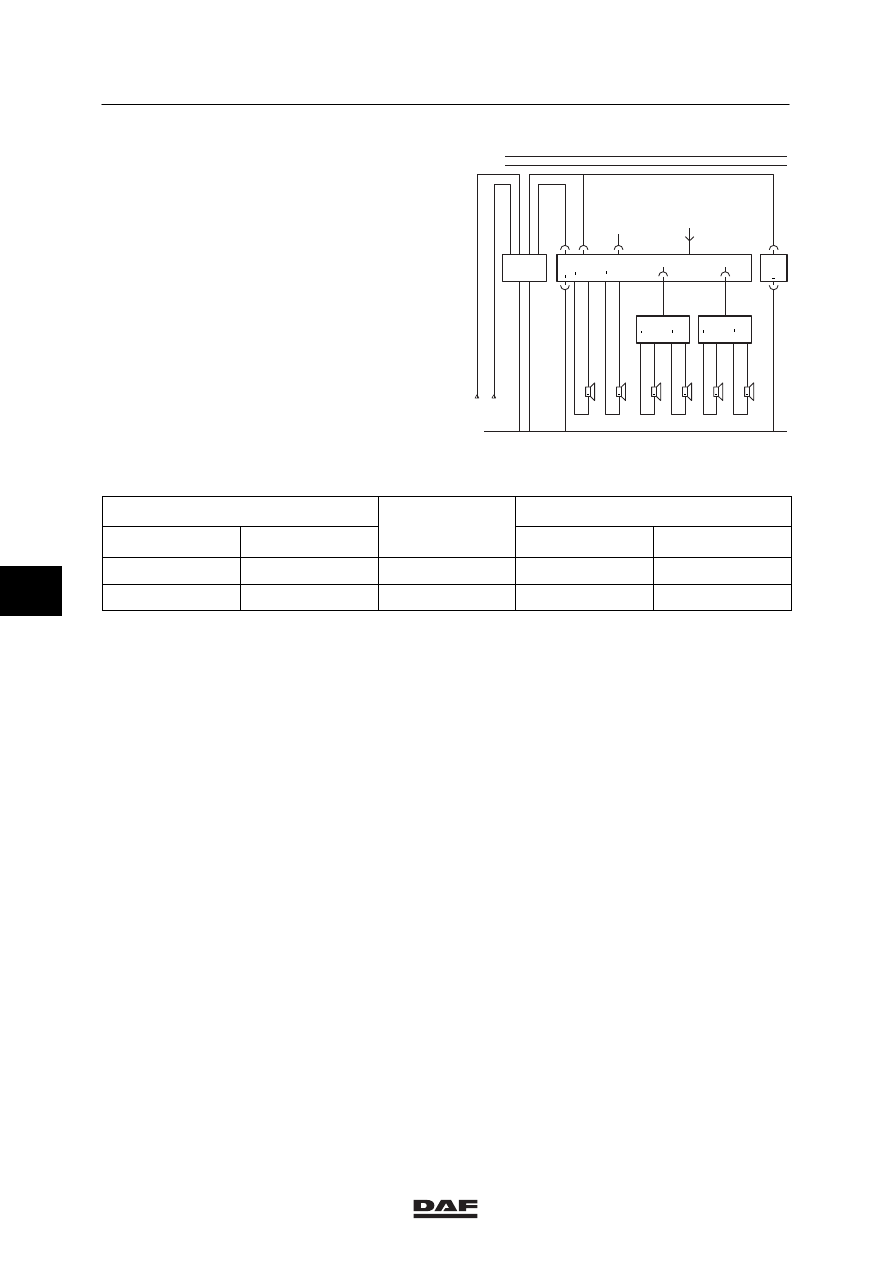
Channel memory of Philips radio
The 12V/10mA output is the supply voltage for
the channel memory (output B1 of the
converter).
+
4832
4831
R1+
R1
B180
+
4834
4833
R2+
R2
B181
B187
B026
12V
+
4828
4827
L1+
L1
B178
+
4541
4543
R+
R
B025
+
4540
4542
L+
L
12V
B
4
B024
+
4830
4829
L2+
L2
B179
B186
B185
D895
12V
24V
1108
1353
2
1
7
6
1000
1010
B1
A4
B2
A3
A1
A2
301 033
M
1
106
1
107
E500730
Note:
Input
Voltage
before/after the
Output
24 V
Wire no.
before/after the
contact
12 V
Wire no.
A2
1106
after
A4
1108
B2
1107
before
B1
1353
Wire 1105 is connected in contact/starter switch
position with relay G178: “accessories”.
6
ǹ 0009
Нет комментариевНе стесняйтесь поделиться с нами вашим ценным мнением.
Текст