DAF 95XF. Manual — part 284
5
Electrical installation
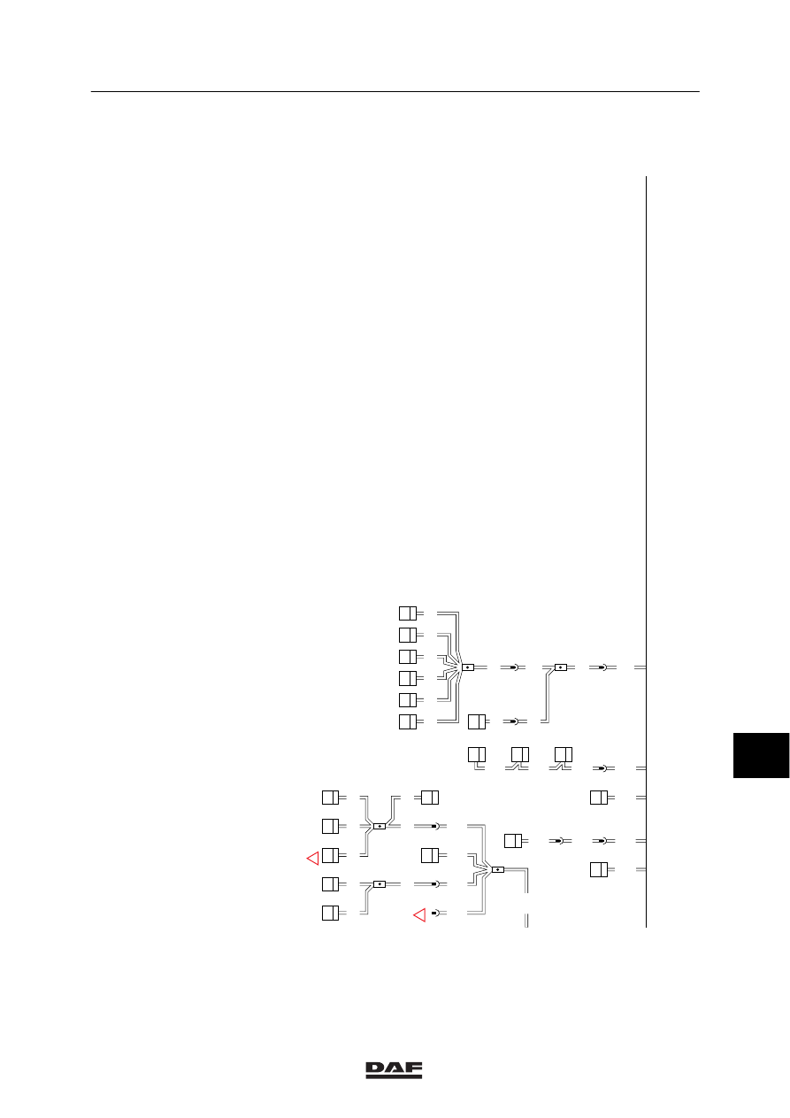
ELECTRICAL INSTALLATION
2-35
C003
2
B130
1
C015
2
C007
2
B042
4
C001
2
M2
M3
M4
M5
M6
M7
C740
1
2
M4
B
1316630/05
EL000094
54
55
56
57
58
59
60
61
62
63
64
65
66
67
68
69
70
71
72
73
74
75
76
77
78
79
80
81
82
83
84
85
86
87
88
89
90
91
92
93
94
96
96
97
98
99
100
101
102
103
104
105
106
M110
A040
12
M115
M120
M116
M117
12
383
!
6
6
277
M1
M2
B018
2
B200
4
M3
12
187
C067
2
M5
C017
2
M6
B033
2
M3
M1
20
185
9108
2
307
9108
9108
D529
2
9107
A021
2
20
376
9009
9009
9001
B501
A5
C742
1
C741
7
9009
9009
18
286
M20
M1
C063
2
M5
3
143
M1
M13
12
288
M1
!
7
10
ǹ 9711
5
ELECTRICAL INSTALLATION
Electrical installation
2-36
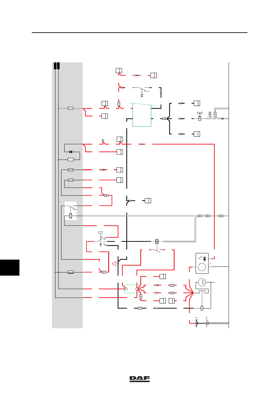
1.
CHARGING CIRCUIT / STARTING MOTOR / CONTACT/STARTER SWITCH
CONTACT CIRCUIT
If contact/starter switch C539 is turned (contact
1 is connected to pin 6), the accessories relay
(G178) will be activated.
Voltage is now applied through fuse E037,
switch C539 and wire 1130 to contact 85 of
relay G178. Because relay G178 is activated, a
connection is made between contacts 30 and 87
and a voltage is applied through fuse E027 and
wire 1106 to pin 1 of the electronic converter 24
V/12V. At the same time a voltage is applied
through fuse E052 and wire 1110 to the
electronic unit of the seat adjustment on
co-driver’s side (B202, pin 2) (if fitted), to the
electronic unit of the seat adjustment on driver’s
side (B197, pin 2) (if fitted), and to pin Pn on the
work light switch (C625).
If the vehicle contact is turned off, no voltage is
applied to connection point 42. As a result, pin
55 of the CTE-2-unit will be connected to the
supply voltage for 3 minutes, causing the engine
stop/engine brake valve (B082) to become
activated.
If the vehicle is switched to contact again, the
engine stop/engine brake valve (B082) is
deactivated again.
For more information on activating the engine
brake: see system manual
START CIRCUIT
If contact switch C539 is turned (contact 1 is
connected to contacts 4 and 6), contact relay
G015 is activated through wire 4001. If the
contact switch is turned into the “starting”
position, a connection between points 1 and 2 is
made in this switch. The supply now runs from
the batteries through fuse E037, connection 1-2
of the contact/starter switch and wire 4002 to
connection point 50 of starting motor B010. The
relay coil is located between points 50 and 31
(earth) and will supply the starting motor with
voltage through connection points 30 and 31, as
a result of which the motor will start operating.
Voltage is also applied to pin 45 of the CTE-2
through fuse E037, wire 1100, switch C539
(connections 1 and 2), wire 4002, fuse E073
and wire 4003. Depending on the condition
(engine speed exceeding approx. 400 rpm and
supply voltage (battery voltage) on the CTE unit
exceeding 17 V), glowing is activated during
starting, on the understanding that preglowing
has taken place first.
For more information on glowing: see system
manual.
10
ǹ 9711
5
Electrical installation
ELECTRICAL INSTALLATION
2-37
CHARGING CIRCUIT
If the contact is activated, voltage is applied to
resistor generator D+ (B036).
The other side of the resistor is connected to
earth through the diode for generator safety
(D+) (D668), wire 1020, D+ connection of the
alternator and the integrated voltage regulator
(A502) in the generator. This will cause a small
current to run, causing a magnetic field in the
alternator.
After starting, the voltage on clamps B+ and D+
will increase to approx. 28.4 V. This is caused
by the fact that the regulator disconnects the
earth connection in the regulator and connects it
to the battery voltage. This voltage is also
applied to wire 1020, so that the difference of
potential over the resistor becomes 0 V. The
magnetic field now disappears, so that the
generator is not activated for a short time. This
will reduce the voltage on outputs B+ and D+.
The regulator is activated if the voltage drops
below 27.6 V. This way, the generator voltage
supply remains relatively constant. The batteries
are fed by generator output B+.
VARIANTS
Location
14 Wire 4009 only applies in the case of a VF
engine.
10
ǹ 9711
5
ELECTRICAL INSTALLATION
Electrical installation
2-38
1202
G243
3
24
1202
A
114
1000
1000
1000
D853
B6
7
1020
1316630/05
EL000095
1
4001
1010
1000
A500
2/233
1/233
15/402
19/402
G525
G525
G014
1
3
1000
27
114
!
4009
4009
4009
1100
1100
1/412
2/412
4/412
6/412
1010
34/400
1020
1020
A040
7
42
1
114
1020
1020
1020
1000
4002
1000
B
114
1000
1000
1000
1100
C539
8
383
30
87
86
85
G015
1000
50
B010
M
31
30
G
3
D
B+
D+
A502
1
23456789
1
0
1
1
1
2
1
3
1
4
1
5
1
6
1
7
1
8
1
9
2
0
2
1
2
2
2
3
2
4
2
5
2
6
2
7
2
8
2
9
3
0
3
1
3
2
3
3
3
4
3
5
3
6
3
7
3
8
3
9
4
0
4
1
4
2
4
3
4
4
4
5
4
6
4
7
4
8
4
9
5
0
5
1
5
2
5
3
1010
1000
20/402
1130
D525
2
35
1106
12/403
1110
3/402
32/400
1/402
C725
5
22
13/402
1
176
1110
10/403
1147
1147
1147
4002
4002
4002
D
114
4
1
B192
4049
4049
1202
1202
55/
232
16/
232
45/
232
42/
232
D550
D813
1
13
D878
1010
1000
E037
15A
1000
1010
D668
B036
1024
1020
30
86
85
87A
8
7
G178
1100
1147
1130
E027
10A
E052
10A
1147
E019
10A
16/402
1202
1202
4002
4002
C726
5
71
01
2
176
1202
1202
10
176
4011
4011
C775
3
4
5
185
1202
E564
2
14
G525
4049
4049
4049
D804
6
30
4049
4049
C754
5
30
10
376
12
114
7
371
E043
A1
23
1000
1000
E168
A1
21
1000
D827
A4
41
2
383
4002
10
ǹ 9711
Нет комментариевНе стесняйтесь поделиться с нами вашим ценным мнением.
Текст