DAF 95XF. Manual — part 285
5
Electrical installation
ELECTRICAL INSTALLATION
2-39
2.
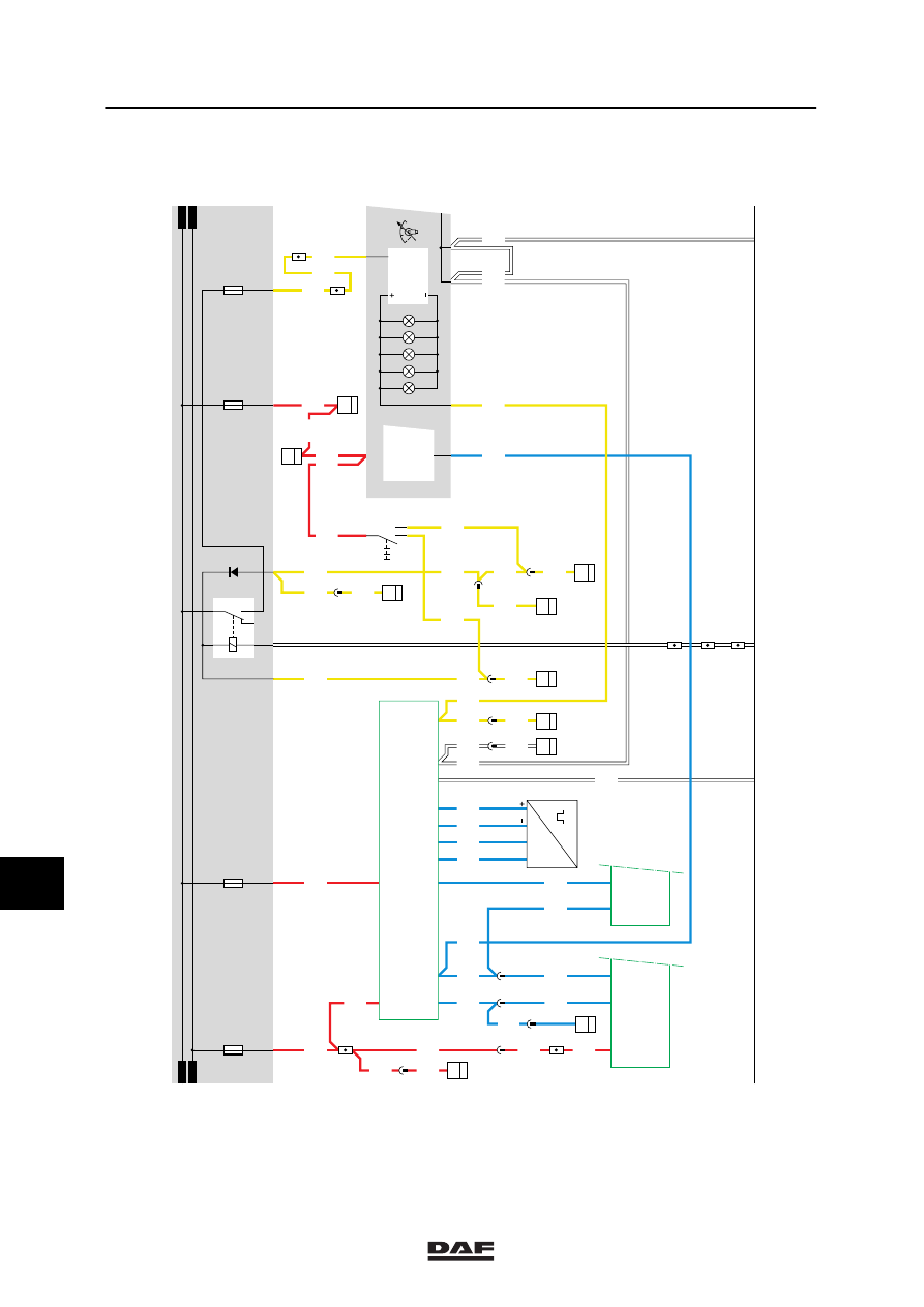
TACHOGRAPH
The tachograph (B501) has two supplies; one in
front of and one behind the contact relay
(G015).
The non-activated supply voltage is applied to
tachograph point 1/223 through fuse E023 and
wire 1127.
This supply voltage is meant for the clock,
among other things.
The activated supply voltage is applied to
tachograph point 3/223 through fuse E143 and
wire 1234.
De tachograph is connected to the vehicle
speed sensor (F533) through points B1 (1/271),
B2 (2/271), B3 (3/271) and B4 (4/271).
Pin B1 (1/271) represents the supply voltage for
speed sensor (4-pin 1st) (F533).
Pin B1 (2/271) is the earth connection for speed
sensor (4-pin 1st) (F533).
Pins B3 (3/271) and B4 (4/271) of the
tachograph receive two speed signals in
opposite phase.
Pin 3/225 of the tachograph supplies a pulsating
speed signal to the CTE 2-unit, connection point
18/232. For more information see system
manual.
Pin B7 (7/271) of the tachograph supplies the
same pulsating speed signal to one of the speed
limiting systems: ASL-V (D597), ASL-G (D809),
the E-gas 3-system (D591) or the
ECS-DS-system (D805). This wire may not be
interrupted or branched. All wiring connections
this wire runs through must be provided with a
seal.
There is also a speed signal (wire 3004) which
is connected to tachograph connection point
4/224 through the instrument panel (D852). This
is to connect a tachograph with speed
registration.
10
ǹ 9711
5
ELECTRICAL INSTALLATION
Electrical installation
2-40
2110
B130
3
33
4
286
2110
2
1316630/05
EL000096
15/202
16/202
12/202
27/400
5/401
2630
2630
2622
3004
17/201
9025
9025
20/202
9025
2630
D853 B15
7
1101
C775
7
10
1101
1101
14/403
2
4
1
C622
1101
1101
1234
23/400
10
378
3514
D805 B07
29
3514
3514
1234
2
378
1234
3004
3
378
3004
3004
3500
3018
3019
3020
3021
9001
1127
31/402
2622
3004
2622
6
371
C052
1
20
2
397
2622
B805 B26
30
3
371
9025
9025
9025
1234
D804 C26
29
1
371
1234
1234
1234
22/401
C773
2
11
2100
2100
4
176
24/401
B129
3
33
2110
2110
4
281
2110
2100
2100
10/201
G525
1
23456789
1
0
1
1
1
2
1
3
1
4
1
5
1
6
1
7
1
8
1
9
2
0
2
1
2
2
2
3
2
4
2
5
2
6
2
7
2
8
2
9
3
0
3
1
3
2
3
3
3
4
3
5
3
6
3
7
3
8
3
9
4
0
4
1
4
2
4
3
4
4
4
5
4
6
4
7
4
8
4
9
5
0
5
1
5
2
5
3
D878
1010
1000
1010
1000
2100
E084
10A
E117
10A
30
86
85
87A
8
7
G000
M
D609
2101
E143
15A
E023
10A
28/
333
11/
333
20/
333
D591
6/
232
18/
232
D550
n
F533
S1
S2
3/
223
4/
224
7/
271
3/
225
1/
271
2/
271
3/
271
4/
271
5/
223
6/
223
1/
223
2/
223
B501
P
µ
D852
M
C773
5
11
2110
2110
2110
5
176
10
ǹ 9711
5
Electrical installation
ELECTRICAL INSTALLATION
2-41
3.
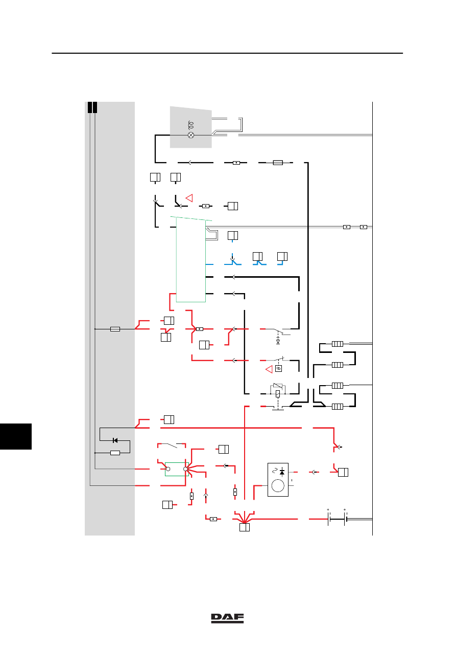
GLOW PLUGS / GLOWING / AFTERGLOWING
GLOWING
Glowing is only required if the outside
temperature is below 5
°C.
Automatic (16/232)
The automatic preglowing time is factory set to
45 seconds.
To protect the glow filaments against
overheating, the circuit of this engine type
contains a thermal protection switch (E550). The
thermal protection switch opens at 110 -125
°C.
Afterglowing
The after-glowing function is applied in Euro-2
engines. The glowing time is factory set to 120
seconds. Afterglowing is started approx.
3 seconds after loss of voltage at connection
point 45 (starting signal).
Afterglowing only takes place if:
-
Preglowing has taken place.
-
The engine speed exceeds approx.
400 rpm.
-
The supply voltage (battery voltage) to the
CTE unit exceeds 17 V.
During afterglowing the CTE unit checks both
the engine speed and the supply voltage. If the
engine speed falls below approx. 400 rpm of if
the supply voltage (battery voltage) falls below
approx. 17 V, the afterglowing is interrupted.
Glowing while starting
During a “starting” action voltage is applied to
pin 45 of the CTE-2 through wire 4002.
Depending on the condition (engine speed
exceeding (6/232) approx. 400 rpm and supply
voltage (battery voltage) (42/232) on the CTE
unit exceeding 17 V), glowing is applied during
starting on the understanding that preglowing
has taken place first.
VARIANTS
Location
21 Component E550 is not present in VF
engines.
41 Wire 4009 only applies in the case of a VF
engine.
SEE THE SYSTEM MANUAL FOR MORE
INFORMATION
10
ǹ 9711
5
ELECTRICAL INSTALLATION
Electrical installation
2-42
G243
3
24
1020
C775
3
4
1020
1316630/05
EL000097
3
1010
1000
2/233
1/233
G525
1000
1010
1000
1020
1020
1020
1000
4015
4018
G525
G525
4014
4014
4061
1202
16/401
1202
19
114
4019
4019
4019
4014
E112
5A
1
2
4013
1202
4011
4011
3004
4014
11
114
30
87
G015
B038
2
1
B039
2
1
B040
2
1
B041
2
1
A040
7
42
30
114
1202
1
114
1020
E550
2
1
13/402
D853
B6
7
1020
8
383
20/202
3/202
1
23456789
1
0
1
1
1
2
1
3
1
4
1
5
1
6
1
7
1
8
1
9
2
0
2
1
2
2
2
3
2
4
2
5
2
6
2
7
2
8
2
9
3
0
3
1
3
2
3
3
3
4
3
5
3
6
3
7
3
8
3
9
4
0
4
1
4
2
4
3
4
4
4
5
4
6
4
7
4
8
4
9
5
0
5
1
5
2
5
3
D591
20
28
3
378
3004
3004
3004
B501
C4
2
D852 A12
6
1000
1000
1020
1000
4013
1000
1000
A
114
B010
30
1
1000
B
114
1000
!
9025
9025
17/201
10
176
2
176
1202
4013
1202
1202
D813
1
13
1202
D827
A4
41
2
383
4002
4002
4002
B010
50
1
DVB
4009
4002
C539
2
1
4002
D878
1010
1000
1000
1010
E019
10A
D668
B036
1024
G014
2
1
85
86
G
3
D
B+
D+
A502
D852
D550
3/
232
16/
232
42/
232
45/
232
28/
232
39/
232
6/
232
C726
5
71
01
A500
!
1000
E043
A1
23
1000
E168
A1
21
1000
1000
10
ǹ 9711
Нет комментариевНе стесняйтесь поделиться с нами вашим ценным мнением.
Текст