DAF 95XF. Manual — part 359
5
MODIFICATIONS TO THE ELECTRICAL INSTALLATION
Modifications to the electrical installation from chassis number 0E477514
4-48
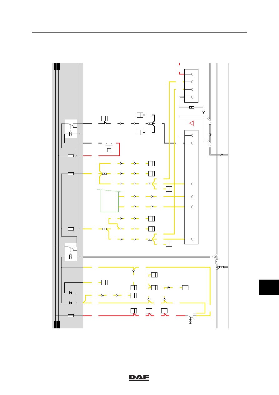
SUPERSTRUCTURE SIDE--LIGHTS
CONNECTOR (A026)
This connector is located in the side member at
the rear left (connector 516).
Pin 1
is connected directly to the
(semi--)trailer socket (A000) pin 2
through wire 2102, and to the
rear--light/ side light relay (G000)
through fuse E000.
Pin 2
is connected directly to the
(semi--)trailer socket (A000) pin 6
through wire 2103, and to the
rear--light/ side light relay (G000)
through fuse E001.
Pin 3
is connected directly to pin 5 of the rear
fog light socket (A001) through wire
1113 and to the supply voltage through
fuse E048.
Pin 4
is connected to earth.
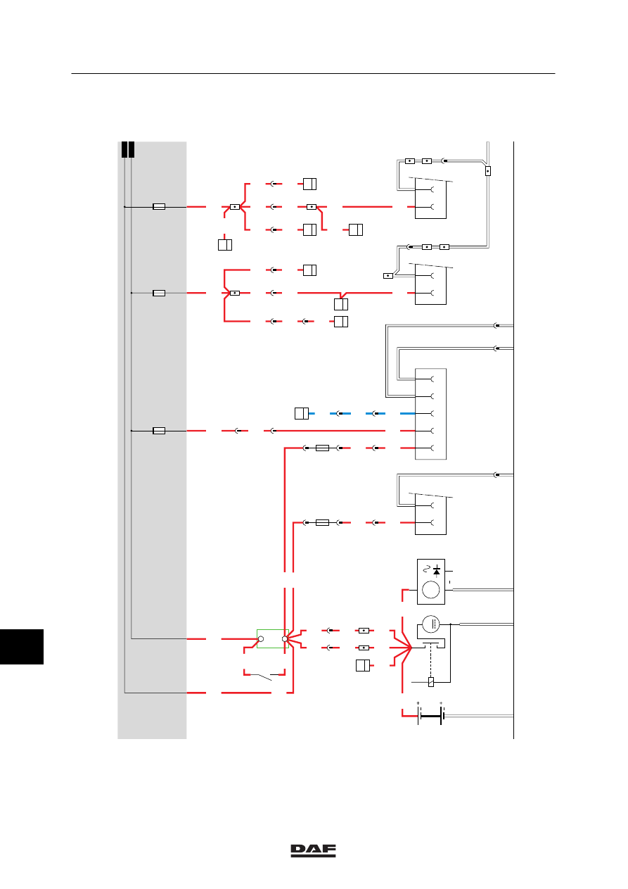
AUTOMATIC GEARBOX (A047)
Pin 1
is connected to contact 87 of relay
G291 through wire 5638.
Pin 2
is connected to contact 87A of relay
G291 through wire 5639.
Pin 3
is connected to contact 30 of relay
G291 through wire 5640.
Pin 4
is connected to contact 30 of relay
G294 through wire 5641.
Pin 5
is connected to contact 87A of relay
G294 through wire 5642.
Pin 6
is connected to contact 87 of relay
G294 through wire 5643.
Pin 7
is connected to the electronic unit for
gearbox control (D866) through wire
5644.
Pin 8
is connected to the PTO control switch
(C714) through wire 5628.
Pin 9
is connected to earth.
VARIANTS
Location
104, 134 In the case of a 15-pin connector,
connectors A000 and A001 are
combined.
The FA trailer connector is installed in
the back cross member of the chassis.
The pins will be allocated as follows:
Pin 1
is connected to the CTE--3 unit (2/232)
(left direction) through wire 2008.
Pin 2
is connected to the CTE--3 unit
(30/232) (right direction) through wire
2009.
Pin 3
(rear fog lights) is connected to the
supply voltage through fuse E010, relay
G005 and wire 2152.
Pin 4
is connected to earth.
11
ǹ 0209
5
Modifications to the electrical installation from chassis number 0E477514
MODIFICATIONS TO THE ELECTRICAL INSTALLATION
4-49
Pin 5
switches the left--hand rear light
through wire 2102. If a connection is
made between contacts 2 and 1
(rear/side marker and parking lights
position) with the lighting switch
(C622), a voltage is applied to contact
85 of relay G000 through fuse E084,
wire 1101, switch C622 and wire 2100.
The relay is activated and a voltage is
applied from wire 1000, contacts 30
and 87 (from relay G000) through fuse
E000 to pin 2 (through wire 2102).
Pin 6
switches the right--hand rear light
through wire 2103. If a connection is
made between contacts 2 and 1
(rear/side marker and parking lights
position) with the lighting switch
(C622), a voltage is applied to contact
85 of relay G000 through fuse E084,
wire 1101, switch C622 and wire 2100.
The relay is activated and a voltage is
applied from wire 1000, contacts 30
and 87 (from relay G000) through fuse
E001 to pin 6 (through wire 2103).
Pin 7
is connected to relay G036 (brake--light
relay) through wire 4601.
Pin 8
is connected to the supply voltage once
the contact has been activated and the
gearbox is in reverse gear. The voltage
is applied as follows: through fuse
E016 (wire 1217), back--up switch
E501 (wire 4591) to pin 3.
Pin 9
is connected directly to the supply
voltage through fuse E048 and wire
1113. Pin 3 is also connected to
connector A026 (superstructure
side--lights, 4--pin).
151
This location provides the power supply
for accessories (M6 bolt on the central
printed circuit).
11
ǹ 0209
5
MODIFICATIONS TO THE ELECTRICAL INSTALLATION
Modifications to the electrical installation from chassis number 0E477514
4-50
1316630/24-29
EL000380
43
1
23456789
1
0
1
1
1
2
1
3
1
4
1
5
1
6
1
7
1
8
1
9
2
0
2
1
2
2
2
3
2
4
2
5
2
6
2
7
2
8
2
9
3
0
3
1
3
2
3
3
3
4
3
5
3
6
3
7
3
8
3
9
4
0
4
1
4
2
4
3
4
4
4
5
4
6
4
7
4
8
4
9
5
0
5
1
5
2
5
3
1240
1240
1240
1240
1240
1240
1240
1240
1240
1000
1000
1010
1000
1000
1000
1000
1000
1000
1000
1000
1175
1000
1175
1000
1119
1119
1000
1010
1288
1288
1288
3428
1000
3428
1181
1181
1181
1181
1181
1181
1181
1181
1181
1181
1181
3428
25/400
1
187
7
185
1
286
1
288
B042
1
22
21
185
A
114
2/233
1/233
G525
G525
G014
1
3
B
114
2
180
1
180
30
87
G015
E168
40A
A2
A1
A
115
E043
25A
A2
A1
B032
1
21
B033
1
21
C
115
27
321
12/401
1
377
1
321
2
321
D853
7
7
35/402
1
196
2
380
D862
10
36
21
380
B199 308
36
1
276
B200 308
36
B030
1
22
A500
50
B010
M
31
30
G
3
D
B+
D+
A502
7
377
D878
E091
15A
1000
1010
1010
1000
E172
10A
E182
15A
A043
12
A038
12
A004
1
2
5
3
4
A042
12
11
ǹ 0209
5
Modifications to the electrical installation from chassis number 0E477514
MODIFICATIONS TO THE ELECTRICAL INSTALLATION
4-51
1316630/24-29
EL000381
43
54
55
56
57
58
59
60
61
62
63
64
65
66
67
68
69
70
71
72
73
74
75
76
77
78
79
80
81
82
83
84
85
86
87
88
89
90
91
92
93
94
96
96
97
98
99
100
101
102
103
104
105
106
4601
4601
1101
1101
2154
1101
1101
2110
2110
2110
2110
2110
2110
2110
2110
2110
2110
2100
2100
2100
2100
2102
2102
2102
2102
2102
2102
2102
2102
2103
2103
2103
2103
2103
2103
2103
2103
2103
2103
2102
4601
4601
4601
2102
2102
1209
4602
2103
2103
2102
2103
4601
2102
2008
2008
2008
2009
2009
2009
2102
2103
1113
4601
4601
14/403
28/401
22/401
5/401
C775
7
10
2/231
1/231
4/231
D853 B15
7
D852 B10
6
24/401
B130
3
33
4
286
4
288
C775
4
10
5
176
4
281
C773
5
11
C764
5
33
B129
3
33
3
284
C727
2
11
4
176
28/400
7
115
3
281
C012
5
8
2
284
5
495
C074
2
2
4
189
C010
1
8
1
161
8
115
C075
2
8
5
189
C011
2
8
2
161
3
286
C013
2
8
3
288
C021
3
14
22
115
C020
3
14
8/402
D759
1
14
33/400
7/402
6/402
12
495
D
115
E511
1
2
P
C622
0II
I
6
495
9
495
5
115
2
495
6
115
4
495
11
495
A000
2
4
1
6
3
5
A026
4
2
3
1
D884
2/
232
30/
232
D878
1010
1000
1010
1000
2100
E084
10A
E000
10A
D609
D610
2154
30
86
85
87A
8
7
G000
2101
E001
10A
M
MM
30
86
85
87A
8
7
G036
4602
E013
10A
1209
!
11
ǹ 0209
Нет комментариевНе стесняйтесь поделиться с нами вашим ценным мнением.
Текст