DAF 95XF. Manual — part 358
5
MODIFICATIONS TO THE ELECTRICAL INSTALLATION
Modifications to the electrical installation from chassis number 0E477514
4-44
42
1316630/24-29
EL000379
213
214
215
216
217
218
219
220
221
222
223
224
225
226
227
228
229
230
231
232
233
234
235
236
237
238
239
240
241
242
243
244
245
246
247
248
249
250
251
252
253
254
2
55
2
56
257
258
2
59
260
2
61
262
263
264
265
4099
3039
3402
3039
9029
1247
1247
4693
4691
4692
1248
1248
1247
1247
4693
4693
4693
4691
4692
4691
4692
4692
4692
4099
4691
4691
4693
1297
1297
1297
1297
1234
1234
3402
1297
1234
1234
1234
3402
1234
3402
3402
4100
1297
13/403
11/403
27/402
D878
1010
1000
1010
1000
E143
15A
E194
5A
E184
5A
1248
1247
G126
87
47
4
398
2
398
3
398
C776
6
79
8
18/
295
21/
295
22/
295
D814
32/
295
34/
295
15/
295
33/
295
F000
2
8
B501
A3
2
4
297
8
297
25/402
2
297
3
297
23/400
G328
1
3
52
4
G321
1
3
42
5
A046
2/534
8/534
5/534
4/534
6/534
3/534
1/534
7/534
11
ǹ 0209
5
Modifications to the electrical installation from chassis number 0E477514
MODIFICATIONS TO THE ELECTRICAL INSTALLATION
4-45
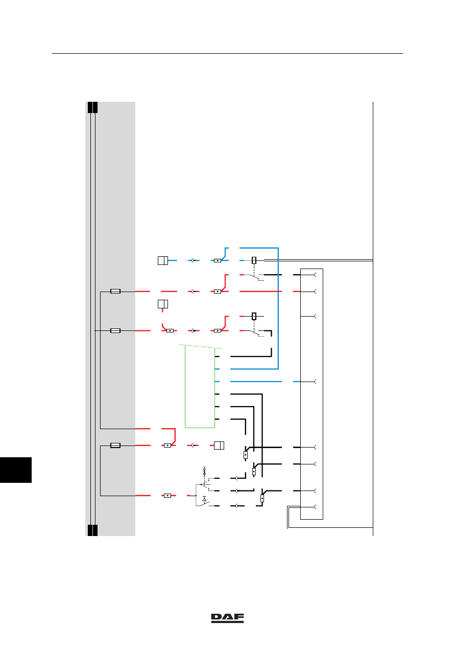
43. CONNECTOR SOCKETS FA, DIAGNOSTIC CONNECTOR, ALARM
CONNECTOR
DIAGNOSTIC CONNECTOR (A021)
The diagnostic connector is installed on the top
left-hand side in the central cabinet. This is the
connector to which DAVIE is connected. After
the contact has been activated, the supply
voltage for DAVIE is applied to pin 1 through
fuse E053. Pin 2 is connected to earth. The
remaining pins are meant for the communication
with various systems and are connected to
those systems.
Pin no.
Wire no.
Colour
Description
1
1229
red
Supply for DAVIE
2
9107
white
Earth
3
3425
blue
ABS/ASC-D
4
4788
black
ASL-G
5
4697
black
ECAS remote control, E-gas 3
6
7
4732
black
ECAS 2
8
9
4047
black
CTE-3
10
11
4883
black
ZF intarder
12
13
3470
blue
AGS
14
3037
blue
D3LC auxiliary heating
24V CONNECTOR (A007)
This 24V connector is located on the right--hand
side, along the air vents of the heater (central
console).
Pin 1
of the 24V connector (A007) is
connected directly to the supply
voltage through wire 1000 and fuse
E036.
Pin 2
is connected to earth.
ABS CONNECTOR (A004)
This ABS connector is installed in the back cross
member of the chassis.
Pin 1
of the ABS connector (A004) is
connected directly to the supply
voltage through wire 1119 and fuse
E043.
Pin 2
is connected directly to the supply
voltage through fuse E040 behind the
contact. This voltage also serves to
feed the ABS unit.
Pins 3,4
are both connected to earth.
Pin 5
is connected to the CWS--2 unit
(D582) through wire 3428.
11
ǹ 0209
5
MODIFICATIONS TO THE ELECTRICAL INSTALLATION
Modifications to the electrical installation from chassis number 0E477514
4-46
FA TRAILER CONNECTOR (7--pin) (A000)
This FA trailer connector is installed in the back
cross member of the chassis.
Pin 1
of the FA trailer connector (A000) is
connected to earth.
If a connection is made between
contacts 2 and 1 (rear/side marker and
parking lights position) with the lighting
switch (C622), a voltage is applied to
contact 85 of relay G000 through fuse
E084, wire 1101, switch C622 and wire
2100. The relay is activated and a
voltage is applied from wire 1000,
contacts 30 and 87 (from relay G000)
through fuses E000 and E001 to pins 2
(through wire 2102) and 6 (through wire
2103) respectively.
Pin 2
switches the left--hand rear light.
Pin 3
is connected to the CTE--3 unit (2/232)
(left direction) through wire 2008.
Pin 4
is connected to relay G036 (brake--light
relay) through wire 4601.
Pin 5
is connected to the CTE--3 unit
(30/232) (right direction) through wire
2009.
Pin 6
switches the right--hand rear light.
REAR FOG LIGHT / BACK--UP LIGHT
CONNECTOR (7--pin) (A001)
This connector is installed in the back cross
member of the chassis.
Pin 1
is connected to earth.
Pin 3
is connected to the supply voltage once
the contact has been activated and the
gearbox is in reverse gear. The voltage
is applied as follows: through fuse
E016 (wire 1217), back--up switch
E501 (wire 4591) to pin 3.
Pin 5
is connected directly to the supply
voltage through fuse E048 and wire
1113. Pin 3 is also connected to
connector A026 (superstructure
side--lights, 4--pin).
Pin 7
(rear fog lights) is connected to the
supply voltage through fuse E010, relay
G005 and wire 2152.
11
ǹ 0209
5
Modifications to the electrical installation from chassis number 0E477514
MODIFICATIONS TO THE ELECTRICAL INSTALLATION
4-47
ALARM SYSTEM SOCKET (A033)
The alarm system socket is located at the front,
below the central printed circuit in the cable
harness.
Pin 1
is connected directly to the supply
voltage in front of the contact through
wire 1114 and fuse E108 (wire 1000).
Pin 2
is connected to the direction indicator,
front left (C014), side direction
indicator, left (C016), direction indicator,
rear left (C018) and the electronic unit
CTE-3 (D884) (4/232) through wire
2006.
Pin 3
is connected to the direction indicator,
front right (C015), side direction
indicator, right (C017), direction
indicator, rear right (C019) and the
electronic unit CTE-3 (D884) (31/232)
through wire 2007.
Pin 4
is connected directly to the control
switch for interior stepwell lighting, door
switch on driver’s side (E514), the
stepwell lighting on driver’s side
(C062), the electronic unit CTE-3
(D884) and the lighting buzzer relay
(G235) through wire 2600.
Pin 5
is connected directly to the stepwell
lighting on co--driver’s side (C063), the
interior lighting switch on co--driver’s
side (C120), the control switch for
interior stepwell lighting, door switch on
co--driver’s side (E515) through wire
2609, and the interior--lighting diode
prevent feedback to the co--driver’s
stepwell (D704).
Pin 6
is connected directly to the cab--lock
control switch (F009) through wire 3412
and to the electronic unit CWS (D582)
(20/215).
Pin 7
is connected directly to the generator of
integrated voltage regulator (A502)
(D+) and to lighting relay D+ (G107)
through wire 1020. At the same time
pin 7 is connected directly to the
lighting buzzer (B242) and to the
electronic unit CWS (D582) (12/214).
Pin 8
is connected to earth.
Pin 9
is not connected.
11
ǹ 0209
Нет комментариевНе стесняйтесь поделиться с нами вашим ценным мнением.
Текст