DAF 95XF. Manual — part 340
5
MODIFICATIONS TO THE ELECTRICAL INSTALLATION
Modifications to the electrical installation from chassis number 0E473500
3-46
36
1316630/13-23
EL000252
54
55
56
57
58
59
60
61
62
63
64
65
66
67
68
69
70
71
72
73
74
75
76
77
78
79
80
81
82
83
84
85
86
87
88
89
90
91
92
93
94
96
96
97
98
99
100
101
102
103
104
105
106
26/400
2
276
1208
1208
2
196
1208
1208
C695
4
18
1208
4521
4520
C696
4
18
1208
4523
6
276
4523
4
196
3
196
4520
4
276
4521
3
276
4520
4521
1208
1208
4521
4520
1208
8
276
4525
7
276
17/401
1207
1207
4522
5
276
4522
4524
4524
4525
4527
6
196
4527
1208
8
196
4525
7
196
1233
1233
4526
5
196
4526
4528
4528
4529
35/401
1233
1233
1233
1207
1207
1207
4525
C746
1
18
C774
2
53
4
1
C743
2
53
4
1
G029
30
85
86
87A
87
G028
30
85
86
87A
8
7
M
2
1
B004
C745
2
53
4
1
G031
30
85
86
87A
87
G030
30
85
86
87A
8
7
M
2
1
B003
D878
1010
1000
1010
1000
E044
10A
E033
15A
E034
15A
11
ǹ 0209
5
Modifications to the electrical installation from chassis number 0E473500
MODIFICATIONS TO THE ELECTRICAL INSTALLATION
3-47
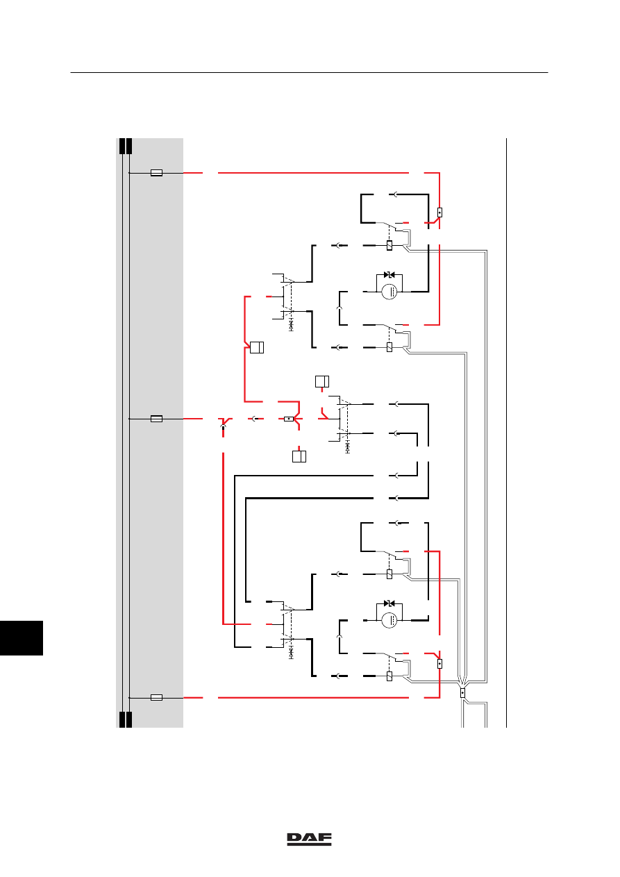
42. CONNECTOR SOCKETS FT
DIAGNOSTIC CONNECTOR (A021)
The diagnostic connector is installed on the
left-hand side in the central cabinet. This is the
connector to which DAVIE is connected. After
the contact has been activated, the supply
voltage for DAVIE is applied to pin 1 through
fuse E053. Pin 2 is connected to earth. The
remaining pins are meant for the communication
with various systems and are connected to
those systems.
Pin no.
Wire no.
Colour
Description
1
1229
Red
Supply for DAVIE
2
9107
White
Earth
3
3425
Blue
ABS/ASC-D
4
4788
Black
ASL-G
5
4697
Black
ECAS remote control / E-gas 3 / ASL-V /
UPEC
6
7
4732
Black
ECAS 2
8
3064
Blue
Connector 378, pin 5
9
4047
Black
CTE–3
10
3065
Blue
Connector 378, pin 4
11
4883
Black
ZF intarder
12
13
3470
Blue
AGS
14
3037
Blue
D1LC / D3LC Compact auxiliary heating/
Hydronic 10
24V CONNECTOR (A042)
Pin 1
of the 24V connector (A042) is
connected directly to the supply
voltage through wire 1000 and
fuse E026.
Pin 2
is connected to earth.
ABS CONNECTOR (A005)
Pin 1
of the ABS connector (A005) is
connected directly to the supply
voltage in front of the contact
through wire 1119 and fuse
E043.
Pin 2
is connected directly to the
supply voltage behind the
contact through fuse E172. This
voltage also serves to feed the
ABS unit.
Pins 3 + 4
are both connected to earth.
Pin 5
is connected to pin 7 of the
CWS-2 unit (D853) through
wire 3428.
11
ǹ 0209
5
MODIFICATIONS TO THE ELECTRICAL INSTALLATION
Modifications to the electrical installation from chassis number 0E473500
3-48
FT TRAILER CONNECTOR (A002)
Pin 1
of the FT trailer connector (A002) is
connected to earth. If a connection is
made between contacts 2 and 1
(rear/side marker and parking lights
position) with the lighting switch
(C622), a voltage is applied to contact
85 of relay G000 through fuse E084,
wire 1101, switch C622 and wire 2100.
The relay is activated and a voltage is
applied from wire 1000, contacts 30
and 87 (from relay G000) through fuses
E000 and E001 to pins 2 (through wire
2102) and 6 (through wire 2103)
respectively.
Pin 2
switches the left-hand rear light.
Pin 3
is connected to the CTE-3 unit (2/232)
(left direction) through wire 2008.
Pin 4
is connected to relay G036 (brake-light
relay) through wire 4601.
Pin 5
is connected to the CTE-3 unit (30/232)
(right direction) through wire 2009.
Pin 6
switches the right-hand rear light.
REAR FOG LIGHT / BACK-UP LIGHT
CONNECTOR (A003)
Pin 1
is connected to earth.
Pin 3
is connected to the supply voltage once
the contact has been activated and the
gearbox is in reverse gear. The voltage
is applied as follows: through fuse
E016 (wire 1217), back-up switch E501
(wire 4591) to pin 3.
Pin 5
is connected directly to the supply
voltage through fuse E048 and wire
1113.
Pin 7
(rear fog lights) is connected to the
supply voltage through fuse E010, relay
G005 and wire 2152.
11
ǹ 0209
5
Modifications to the electrical installation from chassis number 0E473500
MODIFICATIONS TO THE ELECTRICAL INSTALLATION
3-49
ALARM SYSTEM SOCKET (A040)
Pin 1
is connected directly to the supply
voltage in front of the contact through
wire 1114 and fuse E108 (wire 1000).
Pin 2
is connected to the direction indicator,
front left (C014), side direction
indicator, left (C016), direction indicator,
rear left (C018) and the electronic unit
CTE–3 through wire 2006.
Pin 3
is connected to the direction indicator,
front right (C015), side direction
indicator, right (C017), direction
indicator, rear right (C019) and the
electronic unit CTE–3 through wire
2007.
Pin 4
is connected directly to the control
switch for interior stepwell lighting, door
switch on driver’s side (E514), the
stepwell lighting on driver’s side
(C062), the electronic unit CTE–3
(D884) and the lighting buzzer relay
(G235) through wire 2600.
Pin 5
is connected directly to the stepwell
lighting on co-driver’s side (C063), the
interior lighting switch on co-driver’s
side (C686), the control switch for
interior stepwell lighting, door switch on
co-driver’s side (E515) through wire
2609, and the interior-lighting diode
prevent feedback to the co-driver’s
stepwell (D708).
Pin 6
is connected directly to the cab-lock
control switch (F009) through wire 3412
and by means of a cab lock connection
(cab without air suspension) (G719) to
the electronic unit CWS (D582) through
wire 3492.
Pin 7
is connected directly to the generator of
integrated voltage regulator (A502)
(D+) and to lighting relay D+ (G107)
through wire 1020. At the same time
pin 7 is connected directly to the
lighting buzzer (B242) and to the
electronic unit CWS (D582).
Pin 9
is connected to the electronic unit of
the central door locking (D862).
Pin 12
is connected to earth.
11
ǹ 0209
Нет комментариевНе стесняйтесь поделиться с нами вашим ценным мнением.
Текст