DAF 95XF. Manual — part 607
8
TRAILING AXLES
Removal and installation
3-22
8.
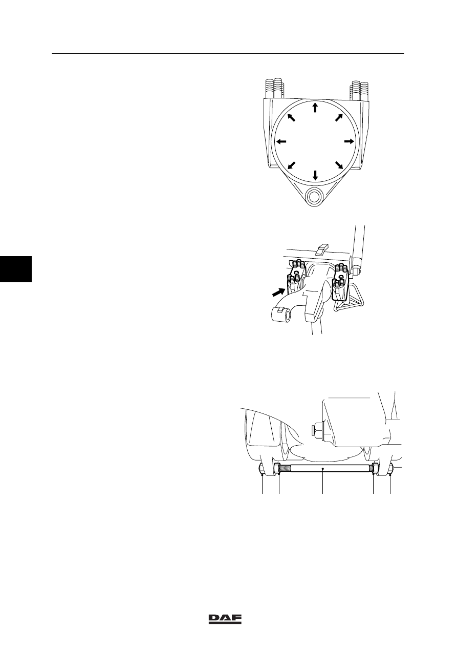
Fit the sealing plate and lock it by tapping
the centring edge inward in eight places.
A8 00 419
9.
Fit the outer bearing block to the axle
journal. Make sure that the push/pull rod is
inserted through the eye of the bearing
block.
A8 00 421
10. Fit the bearing in the outer bearing block.
11. Screw the adjusting nut several turns into
the bearing block.
12. Turn the outer nut (1) of the push/pull rod
onto the push/pull rod.
13. Clean the contact surfaces of the bearing
blocks and bearing support. Check that all
adjusting bushes are present.
1
2
3
4
5
A8 00 407
5
ǹ 200302
8
Removal and installation
TRAILING AXLES
3-23
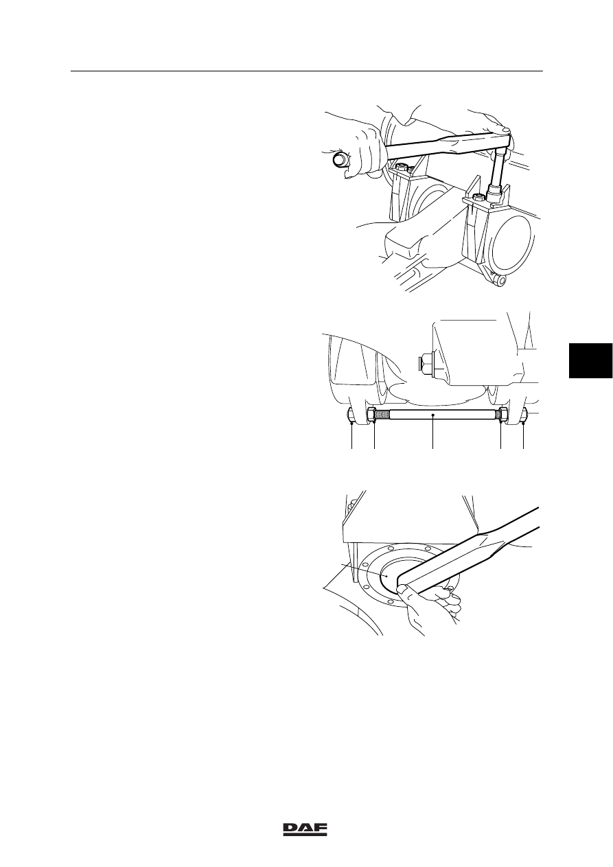
14. Fit the bearing blocks into their original
positions on the bearing support.
Tighten the attachment nuts evenly to the
specified tightening torque. See main group
“Technical data”.
A800219
15. Turn the inner nuts (2 and 4) of the
push/pull rod (3) against the bearing block.
16. Tighten the outer nuts (1 and 5) of the
push/pull rod (3) to the specified tightening
torque, see main group “Technical data”.
1
2
3
4
5
A8 00 407
17. Tighten the adjusting nut to the specified
tightening torque using the special tool (A)
(DAF No. 1453122). See main group
“Technical data”.
18. Loosen the adjusting nut. Retighten the
adjusting nut to the specified tightening
torque. See main group “Technical data”.
A8 00 415
A
ǹ 200302
5
8
TRAILING AXLES
Removal and installation
3-24
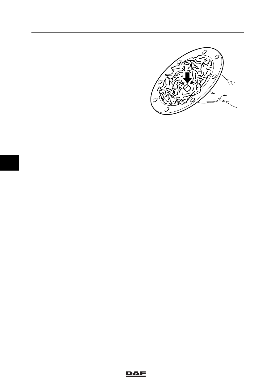
19. Fit a new gasket to the cover and fit the
cover. The lock cam on the inside of the
cover must fall into a recess in the adjusting
nut. If it does not, turn the adjusting nut to
the smallest angle (loosen or tighten) until
the lock cam falls into a recess.
20. Fit the cover attachment bolts.
21. Lubricate the bearing blocks until a collar of
grease is visible at the seals.
A800221
5
ǹ 200302
8
Contents
HYDRAULIC LIFTING GEAR
1
CONTENTS
Page
Date
1.
SAFETY INSTRUCTIONS
1-1
0001
. . . . . . . . . . . . . . . . . . . . . . . . . . . . . . . . . . . . . . . . . . . . . . .
. . . . . .
2.
GENERAL
2-1
0001
. . . . . . . . . . . . . . . . . . . . . . . . . . . . . . . . . . . . . . . . . . . . . . . . . . . . . . . . . . . .
. . . . . .
2.1
Location of components
2-1
0001
. . . . . . . . . . . . . . . . . . . . . . . . . . . . . . . . . . . . . . . . . . .
. . . . . .
2.2
System description, hydraulic part
2-2
0001
. . . . . . . . . . . . . . . . . . . . . . . . . . . . . . . . . . .
. . . . . .
2.3
Overview drawing, pump unit
2-4
0001
. . . . . . . . . . . . . . . . . . . . . . . . . . . . . . . . . . . . . . .
. . . . . .
2.4
Overview drawing, 2/2 magnetic valve
2-6
0001
. . . . . . . . . . . . . . . . . . . . . . . . . . . . . . .
. . . . . .
2.5
Overview drawing, 4/2 magnetic valve
2-7
0001
. . . . . . . . . . . . . . . . . . . . . . . . . . . . . . .
. . . . . .
2.6
Overview drawing, pressure relief valve
2-8
0001
. . . . . . . . . . . . . . . . . . . . . . . . . . . . . .
. . . . . .
2.7
Overview drawing, cylinder
2-9
0001
. . . . . . . . . . . . . . . . . . . . . . . . . . . . . . . . . . . . . . . . .
. . . . . .
3.
INSPECTION AND ADJUSTMENT
3-1
0001
. . . . . . . . . . . . . . . . . . . . . . . . . . . . . . . . . . . . . . .
. . . . . .
3.1
Inspection, system pressure and pressure switch
3-1
0001
. . . . . . . . . . . . . . . . . . . . . .
. . . . . .
3.2
Inspection and adjustment, pressure-relief valve
3-2
0001
. . . . . . . . . . . . . . . . . . . . . . .
. . . . . .
3.3
Inspection, internal leakage pump unit
3-4
0001
. . . . . . . . . . . . . . . . . . . . . . . . . . . . . . .
. . . . . .
3.4
Bleeding of the hydraulic lifting gear
3-5
0001
. . . . . . . . . . . . . . . . . . . . . . . . . . . . . . . . .
. . . . . .
3.5
Inspection, fluid level in the hydraulic lifting gear
3-5
0001
. . . . . . . . . . . . . . . . . . . . . . .
. . . . . .
3.6
Inspection, cylinder
3-6
0001
. . . . . . . . . . . . . . . . . . . . . . . . . . . . . . . . . . . . . . . . . . . . . . . .
. . . . . .
4.
REMOVAL AND INSTALLATION
4-1
0001
. . . . . . . . . . . . . . . . . . . . . . . . . . . . . . . . . . . . . . . . .
. . . . . .
4.1
Removal and installation, pump unit
4-1
0001
. . . . . . . . . . . . . . . . . . . . . . . . . . . . . . . . .
. . . . . .
4.2
Removal and installation, 4/2 magnetic valve
4-3
0001
. . . . . . . . . . . . . . . . . . . . . . . . .
. . . . . .
4.3
Removal and installation, 2/2 magnetic valve
4-4
0001
. . . . . . . . . . . . . . . . . . . . . . . . .
. . . . . .
4.4
Removal and installation, pressure-relief valve
4-5
0001
. . . . . . . . . . . . . . . . . . . . . . . .
. . . . . .
4.5
Removal and installation, cylinder
4-6
0001
. . . . . . . . . . . . . . . . . . . . . . . . . . . . . . . . . . .
. . . . . .
5.
DISASSEMBLY AND ASSEMBLY
5-1
0001
. . . . . . . . . . . . . . . . . . . . . . . . . . . . . . . . . . . . . . . .
. . . . . .
5.1
Disassembly and assembly, oil pump
5-1
0001
. . . . . . . . . . . . . . . . . . . . . . . . . . . . . . . .
. . . . . .
5.2
Disassembly and assembly, 2/2 magnetic valve
5-4
0001
. . . . . . . . . . . . . . . . . . . . . . .
. . . . . .
5.3
Disassembly and assembly, cylinder
5-6
0001
. . . . . . . . . . . . . . . . . . . . . . . . . . . . . . . . .
. . . . . .
6.
DRAINING AND FILLING
6-1
0001
. . . . . . . . . . . . . . . . . . . . . . . . . . . . . . . . . . . . . . . . . . . . . . .
. . . . . .
6.1
Filling, hydraulic lifting gear
6-1
0001
. . . . . . . . . . . . . . . . . . . . . . . . . . . . . . . . . . . . . . . . .
. . . . . .
ǹ 0001
6
Нет комментариевНе стесняйтесь поделиться с нами вашим ценным мнением.
Текст