DAF 95XF. Manual — part 355
5
MODIFICATIONS TO THE ELECTRICAL INSTALLATION
Modifications to the electrical installation from chassis number 0E477514
4-32
40A
1316630/24-29
EL000356
1
23456789
1
0
1
1
1
2
1
3
1
4
1
5
1
6
1
7
1
8
1
9
2
0
2
1
2
2
2
3
2
4
2
5
2
6
2
7
2
8
2
9
3
0
3
1
3
2
3
3
3
4
3
5
3
6
3
7
3
8
3
9
4
0
4
1
4
2
4
3
4
4
4
5
4
6
4
7
4
8
4
9
5
0
5
1
5
2
5
3
1156
1156
1156
4939
9003
4941
5117
1156
3037
3037
3462
3462
3462
4936
4936
4936
4660
4660
4660
4660
1156
4935
4935
12/
269
3/
269
10/
269
14/
269
2/
269
E566
7/
269
11/
269
D871
5/
482
4/
482
12/
482
3/
482
7/
482
13/
482
8/
482
14/
482
11/
482
D878
1010
1000
1010
1000
E114
15A
12
483
34/402
1
483
11
483
6
483
31
115
4
483
7
397
15
380
C778
5
71
0I
5
380
1156
30
115
5
483
A021
14
B122
M
2
1
D703
2
D704
2
D705
2
!
!
!
11
ǹ 0209
5
Modifications to the electrical installation from chassis number 0E477514
MODIFICATIONS TO THE ELECTRICAL INSTALLATION
4-33
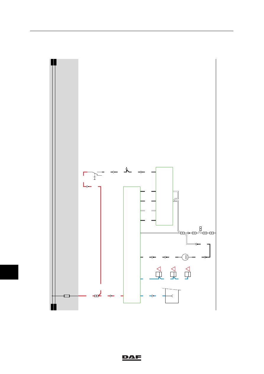
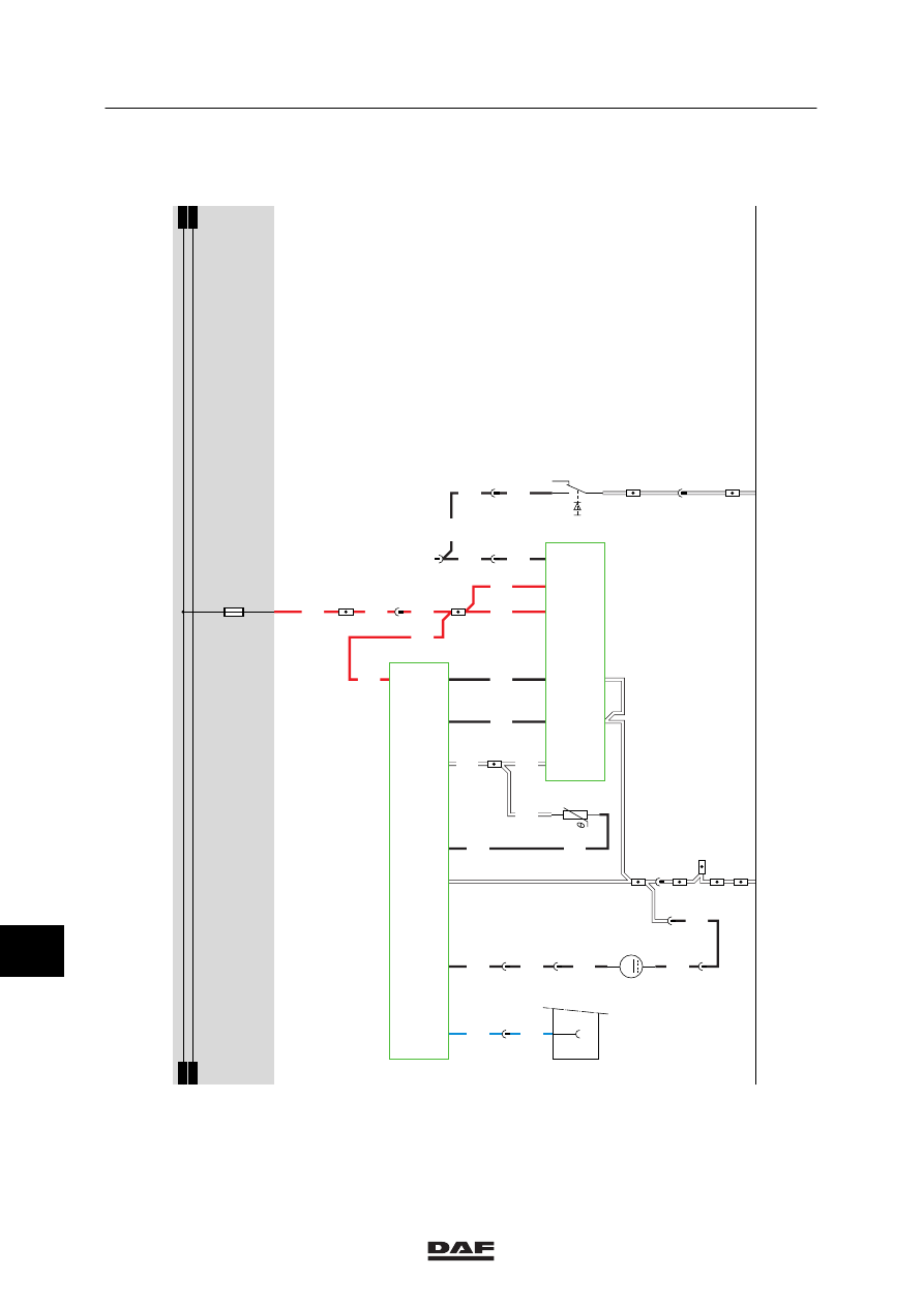
40B. AUXILIARY HEATING EBERSPÄCHER (with timer)
The auxiliary air heating is a separate heating
which functions entirely independent of the
vehicle. The cab temperature is measured by a
temperature sensor (F509). This sensor sends a
signal to the electronic unit D871 which controls
the heating.
As a result, the cab temperature automatically
remains at the preset temperature. In that case,
the blower is in continuous operation.
OPERATION OF AUXILIARY HEATING
The auxiliary air heating can be activated using
switch C844. A green lamp in the timer unit will
light up if the system is activated by means of
this switch.
If the heating is activated, it activates the fan in
the heating unit.
At the same time the fuel metering pump for the
auxiliary Eberspächer heating (B122) is
activated, so that the correct amount of fuel is
fed to the ignition chamber of the heating unit.
If the fuel is ignited, the temperature sensor
(F509) will apply a voltage to electronic unit
D871 through wire 4941 so that at a certain
temperature, the heating unit (D871) switches
off.
If the sensor measures a lower temperature
than the temperature preset by the driver (using
the temperature control button on the timer unit),
the heating power will be adjusted.
In the case of overheating, the thermal
protection will switch off the fuel pump. This will
switch off the heating.
11
ǹ 0209
5
MODIFICATIONS TO THE ELECTRICAL INSTALLATION
Modifications to the electrical installation from chassis number 0E477514
4-34
40B
1316630/24-29
EL000363
1
23456789
1
0
1
1
1
2
1
3
1
4
1
5
1
6
1
7
1
8
1
9
2
0
2
1
2
2
2
3
2
4
2
5
2
6
2
7
2
8
2
9
3
0
3
1
3
2
3
3
3
4
3
5
3
6
3
7
3
8
3
9
4
0
4
1
4
2
4
3
4
4
4
5
4
6
4
7
4
8
4
9
5
0
5
1
5
2
5
3
1156
1156
1156
1156
1156
4939
9003
9003
9003
5117
1156
1156
3037
3037
4936
4936
4941
4941
4936
4660
4660
4660
4660
4660
4935
4935
6/
269
4/
269
9/
269
2/
269
E581
7/
269
10/
269
11/
269
12/
269
D871
5/
482
4/
482
3/
482
7/
482
8/
482
13/
482
14/
482
11/
482
D878
1010
1000
1010
1000
E114
15A
12
483
34/402
1
483
11
483
6
483
31
115
4
483
15
380
21
380
30
115
5
483
A021
14
B122
M
2
1
2
1
F509
7
397
C844
4
I0
28
11
ǹ 0209
5
Modifications to the electrical installation from chassis number 0E477514
MODIFICATIONS TO THE ELECTRICAL INSTALLATION
4-35
42. CONNECTOR SOCKETS FT, DIAGNOSTIC CONNECTOR, ALARM
CONNECTOR
DIAGNOSTIC CONNECTOR (A021)
The diagnostic connector is installed on the
left--hand side in the central cabinet. This is the
connector to which DAVIE is connected. After
the contact has been activated, the supply
voltage for DAVIE is applied to pin 1 through
fuse E053. Pin 2 is connected to earth. The
remaining pins are meant for the communication
with various systems and are connected to
those systems.
Pin no.
Wire no.
Colour
Description
1
1229
red
Supply for DAVIE
2
9107
white
Earth
3
3425
blue
ABS/ASC-D
4
4788
black
ASL-G
5
4697
black
ECAS remote control, E-gas 3
6
7
4732
black
ECAS 2
8
9
4047
black
CTE-3
10
11
4883
black
ZF intarder
12
13
3470
blue
AGS
14
3037
blue
D3LC auxiliary heating
15
16
ABS CONNECTOR (A005)
This ABS connector is located at the rear of the
cab.
Pin 1
of the ABS connector (A005) is
connected directly to the supply
voltage through wire 1119 and fuse
E043.
Pin 2
is connected directly to the supply
voltage after contact through fuse
E040. This voltage also serves to feed
the ABS unit.
Pins 3, 4 are both connected to earth.
Pin 5
is connected to pin 7 of the CWS--2
unit (D582) through wire 3428.
11
ǹ 0209
Нет комментариевНе стесняйтесь поделиться с нами вашим ценным мнением.
Текст