DAF 95XF. Manual — part 354
5
MODIFICATIONS TO THE ELECTRICAL INSTALLATION
Modifications to the electrical installation from chassis number 0E477514
4-28
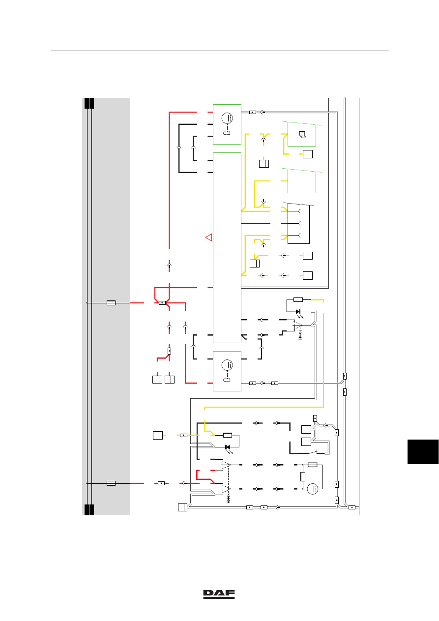
Description of central door locking, driver’s
side (B199) and central door locking motor,
co-driver’s side (B200).
The description of both components is similar to
description B200 as above.
Starting position: both doors locked.
Unlock the co-driver’s side door using the key.
This is the same as the standard version. The
other door remains locked.
Unlock the co-driver’s side door using switch
C803.
If switch C803 is engaged (connection between
pin 1 and 5/3), connection DO of component
B200 is connected to earth. B200 is activated in
the same way as in the standard version.
Starting position: both doors unlocked.
Driver’s side door locked using key/button.
The action is similar to that in the standard
version; in this case, however, unit D862 will
measure an earth signal through connection DL
(wire 4538) to pin 1. D862 now connects pin 2 to
earth, also activating B200. The co-driver’s side
door is now also locked.
Locking co-driver’s side door using key/button.
The operation is the same as the operation
described above. However, unit D862 now
measures an earth signal at pin 2 and will,
therefore, connect pin 1 of component B199 to
earth. The driver’s side door is now also locked.
Note:
If one or both door switches sends a positive
signal to pin 3 or 4 of unit D862, the
accompanying components B199 and/or B200
will not be activated.
11
ǹ 0209
5
Modifications to the electrical installation from chassis number 0E477514
MODIFICATIONS TO THE ELECTRICAL INSTALLATION
4-29
36
1316630/24-29
EL000364
1
23456789
1
0
1
1
1
2
1
3
1
4
1
5
1
6
1
7
1
8
1
9
2
0
2
1
2
2
2
3
2
4
2
5
2
6
2
7
2
8
2
9
3
0
3
1
3
2
3
3
3
4
3
5
3
6
3
7
3
8
3
9
4
0
4
1
4
2
4
3
4
4
4
5
4
6
4
7
4
8
4
9
5
0
5
1
5
2
5
3
1104
1104
2630
2630
1105
1105
1105
1105
1105
4538
4538
4537
5062
5062
1105
1105
1105
1105
1105
1105
1105
4537
2630
4761
4760
4706
4761
4760
4706
4761
4760
4706
5061
5061
5061
5061
5118
5118
2630
2609
2609
2609
2609
2609
2609
2609
2609
2600
2600
5063
2600
2600
2600
2600
2600
1104
1104
4706
D878
1010
1000
1010
1000
E030
10A
E026
15A
0
C736
3
71
82
6
II
I
BA
B175
M
4
2
1
3
308
DO
31
B200
1
2
4
DL
3
M
2/
394
8/
394
6/
394
10/
394
D862
1/
394
7/
394
5/
394
4/
394
3/
394
9/
334
0
C803
5
17
II
I
BA
A040
594
D550
17/
232
308
31
B199
1
4
DL
3
DO
2
M
D853
5/
396
29/402
1
380
6
191
5
191
4
191
18
189
17
189
16
189
E117
2
19
35/402
2
380
1
276
20
380
6
277
5
197
4
197
5
277
4
277
B030
1
22
A042
1
42
1
196
6
380
8
189
8
190
D708
1
17
10
483
E515
2
17
C063
1
17
9
286
9
383
9
281
C062
1
16
E514
1
16
6
197
21
380
C733
B
17
C130
3
17
C149
3
17
12
194
!
11
ǹ 0209
5
MODIFICATIONS TO THE ELECTRICAL INSTALLATION
Modifications to the electrical installation from chassis number 0E477514
4-30
36
1316630/24-29
EL000365
54
55
56
57
58
59
60
61
62
63
64
65
66
67
68
69
70
71
72
73
74
75
76
77
78
79
80
81
82
83
84
85
86
87
88
89
90
91
92
93
94
96
96
97
98
99
100
101
1
02
103
104
105
106
1208
1208
1208
1208
1208
4521
4520
1208
4523
4523
4520
4521
1208
4521
4520
1208
4525
1207
1207
4522
4522
4524
4524
4525
4527
4527
1208
4525
1233
1233
4526
4526
4528
4528
4529
1233
1233
1233
1207
1207
1207
4525
D878
1010
1000
1010
1000
E044
10A
E033
15A
E034
15A
26/400
2
276
2
196
C695
4
18
C696
4
18
6
276
4
196
3
196
4
276
3
276
4520
4521
1208
8
276
7
276
17/401
5
276
6
196
8
196
7
196
5
196
35/401
C746
1
18
C774
2
53
4
1
C743
2
53
4
1
G029
30
85
86
87A
87
G028
30
85
86
87A
87
M
2
1
B004
C745
2
53
4
1
G031
30
85
86
87A
8
7
G030
30
85
86
87A
8
7
M
2
1
B003
11
ǹ 0209
5
Modifications to the electrical installation from chassis number 0E477514
MODIFICATIONS TO THE ELECTRICAL INSTALLATION
4-31
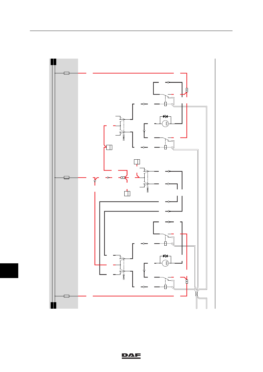
40A. AUXILIARY HEATING EBERSPÄCHER (with thermostat unit)
The auxiliary air heating is a separate heating
which functions entirely independent of the
vehicle. The cab temperature is measured by a
temperature sensor which is installed in the
thermostat unit (E566). This sensor sends a
signal to the electronic unit (D871) which
controls the heating.
As a result, the cab temperature automatically
remains at the preset temperature. In that case,
the blower is in continuous operation.
OPERATION OF AUXILIARY HEATING
The auxiliary air heating can be activated using
the button on thermostat unit E566. If this button
is switched to the “interior heating” position, the
heating will be activated. A green lamp will now
light up in the thermostat unit.
If the heating is activated, it activates the fan in
the heating unit.
At the same time the fuel metering pump for the
auxiliary Eberspächer heating (B122) is
activated, so that the correct amount of fuel is
fed to the ignition chamber of the heating unit.
If the fuel is ignited, a temperature sensor
(installed in the thermostat unit) will apply a
voltage to the heating unit so that at a certain
temperature, the heating unit switches off.
If the sensor measures a lower temperature
than the temperature preset by the driver (using
the temperature control button on the thermostat
unit), the heating power will be adjusted.
In the case of overheating, the thermal
protection will switch off the fuel pump. This will
switch off the heating.
VARIANTS
Location
10 Only applicable when transporting
hazardous substances.
11
ǹ 0209
Нет комментариевНе стесняйтесь поделиться с нами вашим ценным мнением.
Текст