DAF 95XF. Manual — part 292
5
Electrical installation
ELECTRICAL INSTALLATION
2-67
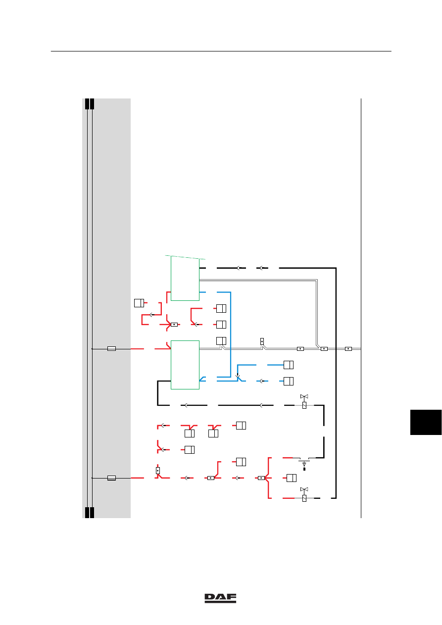
13. GEARBOX AND GATE SAFETY
GROUP SAFETY GEARBOX (gears 1 -> 5)
This shift-down safety prevents shifting down
into the lower group (gears 1, 2, 3 and 4) once
the vehicle speed has exceeded approx. 30
km/h. The shift-down safety is installed on
vehicles with single H-type gearing.
In the case of an electrical malfunction (voltage
drop out), the safety is activated and the gears
1, 2, 3 and 4 cannot be re-engaged.
OPERATION
If the relay contact (G015) is closed, the supply
voltage will be applied to the group safety valve
(“single H” valve) (B079) through fuse E016. As
soon as the CTE-2 unit of the tachograph
receives a signal which corresponds to a vehicle
speed of less than 30 km/h, the CTE 2 will
switch the voltage to earth. As a result, the
group safety valve is activated and shifting down
into a lower group becomes possible.
If the vehicle speed exceeds 30 km/h, the
CTE-2 unit will break the earth connection and
shifting down is no longer possible.
GATE SAFETY (gears 4 -> 1)
If the relay contact (G015) is closed, the supply
voltage will be applied to the control switch
(E561) through fuse E016.
If the low group is activated, switch E561 is
closed and a voltage is applied to valve B293. A
supply voltage is applied to point 1 of electronic
unit D813 through fuse E019 and wire 1202.
Connection 3 of electronic unit D813 is
connected to the CTE-2. This is the
speed-dependent signal. Depending on the
speed, the electronic unit of the gearbox and
gate safety (D813) connects valve B293 to
earth. If both conditions are present, valve B293
is activated and the gate safety is active.
Shifting down from 3rd and 4th gear into the 1st
and 2nd gear is now impossible.
10
ǹ 9711
5
ELECTRICAL INSTALLATION
Electrical installation
2-68
If the high group is activated, switch E561 is
opened and the voltage to valve B293 drops
out. At a speed in excess of approx. 12 km/h,
pin 4 of the electronic unit D813 is
uninterruptedly connected to earth. Shifting
down into 5th or 6th gear is possible, however.
SEE THE CTE SYSTEM MANUAL FOR MORE
INFORMATION
10
ǹ 9711
5
Electrical installation
ELECTRICAL INSTALLATION
2-69
13
1316630/05
EL000110
13/401
1217
C748
5
15
1
118
E501
2
12
1217
1217
4988
35
115
E561
4
2
1217
4988
1217
F006
1
15
1217
1217
1
115
1217
1217
1217
2
376
1217
D749
5
15
1217
1217
3
376
1217
1217
C750
5
15
1217
C751
5
15
16/401
1202
2
1
B079
4030
1
2
B293
4978
D813
3/
134
4/
134
2/
134
1/
134
7
118
4988
3502
D587
5
33
3502
D802
22
25
2
461
5
445
3502
3502
D550
28/
232
19/
232
42/
232
51/
232
3502
3502
4030
33
115
4030
5
118
4030
E550
1
5
1202
1202
30
114
1202
1202
C726
5
3
2
176
1202
1202
C775
3
4
1202
D862
9
36
D878
1010
1000
1010
1000
E016
10A
E019
10A
1
23456789
1
0
1
1
1
2
1
3
1
4
1
5
1
6
1
7
1
8
1
9
2
0
2
1
2
2
2
3
2
4
2
5
2
6
2
7
2
8
2
9
3
0
3
1
3
2
3
3
3
4
3
5
3
6
3
7
3
8
3
9
4
0
4
1
4
2
4
3
4
4
4
5
4
6
4
7
4
8
4
9
5
0
5
1
5
2
5
3
10
ǹ 9711
5
ELECTRICAL INSTALLATION
Electrical installation
2-70
14. BRAKE LIGHTS / CAB AIR SUSPENSION
BRAKE LIGHTS
If the brake pedal is pressed, brake light control
switch E511 is activated and the relay (G036)
will be activated. A voltage will be applied to the
right- and left-hand vehicle brake lights (C021
and C020 respectively) and they will light up.
The lights connected through trailer connector
socket A000 will also light up.
A voltage will also be applied to the CTE unit
(13/232) through diode D722. A voltage is also
applied to connection point 5 of relay G297 (cab
air suspension) through diode D759.
CONTINUOUS BRAKE (engine brake)
If the engine brake control switch (E564) is
activated, a voltage is applied to connection
point 14. As a result, connection point 55 is
activated causing engine brake valve B192 to
become activated.
Connection point 55 is only connected to the
supply voltage if:
-
The engine speed exceeds 700 rpm.
-
The rear wheels do not block in an
ABS-equipped vehicle.
CAB AIR SUSPENSION
A voltage is applied to both the cab lock sensor
(F616) and relay G297 through fuse E030 and
wire 1104. If the cab is tilted, points 2 and 4 in
the cab lock sensor (F616) are connected. As a
result, relay G297 (cab air suspension relay) is
activated through wire 3412 and the cab lock
sensor (F616). The contacts of relay G297 close
(connection between contacts 3 and 5). A
voltage is now applied to valve B294 causing
this valve to become activated as well.
VARIANTS
Location
12,14,16 Connector 495 is only used in the case
of an FA version. In FT versions, wire
4601 (to C021 and C022) and earth do
not run through connector 495.
20
Connector A000 is only used in the
case of an FA. In FT versions,
connector A002 is used.
10
ǹ 9711
Нет комментариевНе стесняйтесь поделиться с нами вашим ценным мнением.
Текст