DAF 95XF. Manual — part 293
5
Electrical installation
ELECTRICAL INSTALLATION
2-71
3412
5/401
14
1316630/05
EL000111
7/402
1209
4602
4602
16/401
E511
2
1
P
6/402
8/402
26/401
3475
4051
1202
1202
E564
1
3
2
1202
1202
D591
20
28
B192
1
1
4049
1202
C726
5
3
10/402
4601
22
115
4601
9
495
4601
4601
4601
D
115
11
495
12
495
C021
3
8
C020
3
8
4601
4601
!
!
!
!
11
185
4051
12
114
4049
4049
3475
D721
2
28
3
378
3004
B501
C4
2
3004
D852 A12
6
3004
3004
2
176
D813
1
13
1202
C775
3
4
1202
5
185
1202
29/402
1104
1104
1104
29/401
3412
3412
10
281
11
285
3412
25/401
3492
D853 A11
7
4589
14/402
C775
8
22
1104
1
281
8
285
1104
1104
1104
1
189
1
190
1104
1104
1104
C151
1
16
1104
C151
2
16
1
380
1104
C736
1
36
1104
C736
8
36
1104
4589
4589
3412
15
281
9
284
4589
4589
4589
12
284
18
281
12
285
3412
2
1
B294
1
23456789
1
0
1
1
1
2
1
3
1
4
1
5
1
6
1
7
1
8
1
9
2
0
2
1
2
2
2
3
2
4
2
5
2
6
2
7
2
8
2
9
3
0
3
1
3
2
3
3
3
4
3
5
3
6
3
7
3
8
3
9
4
0
4
1
4
2
4
3
4
4
4
5
4
6
4
7
4
8
4
9
5
0
5
1
5
2
5
3
14/
232
13/
232
55/
232
6/
232
D550
A000
14
G297
3
1
24
5
F616
1
4
2
D878
1010
1000
1010
1000
E019
10A
30
86
85
87A
8
7
G036
4602
E013
10A
1209
D722
3475
M
D759
4589
E030
10A
D758
3412
10
ǹ 9711
5
ELECTRICAL INSTALLATION
Electrical installation
2-72
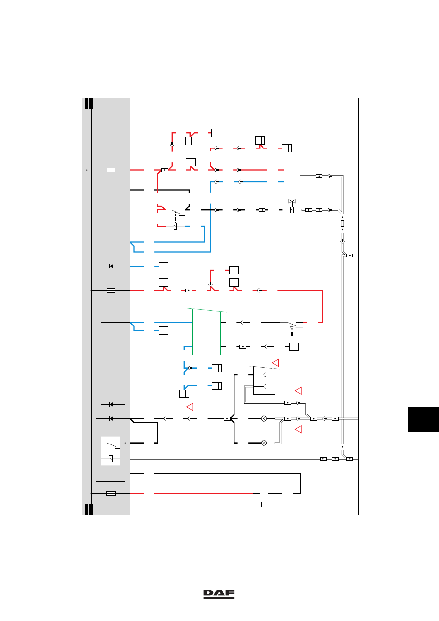
15. DIFFERENTIAL LOCK
1ST, 2ND AND 3RD DIFFERENTIAL LOCK
If the contact switch (G015) is activated, a
voltage is applied through fuse E016 and wire
1217 to the control switch for the axial controlled
slip differential (C748) and control switch for the
longitudinal controlled slip differential (C749).
If the driver now activates the axial controlled
slip differential (C748), a voltage is applied
through wire 4517 to the axial controlled slip
differential valve. As a result, the valve is
activated.
If the driver now activates the longitudinal
controlled slip differential (C749), a voltage is
applied through wire 4518 to the longitudinal
controlled slip differential valve. As a result, the
valve is activated.
If the driver engages the first differential, the
“differential lock control switch” (F006) is
activated. The corresponding symbol on the DIP
will now light up.
10
ǹ 9711
5
Electrical installation
ELECTRICAL INSTALLATION
2-73
15
1316630/05
EL000112
1217
13/401
D878
1010
1000
1010
1000
E016
10A
1217
2
376
1217
1217
3
176
1
118
1217
1217
1217
12
376
4518
2
282
4518
2
525
7
285
4518
4518
1
525
6
285
4517
11
176
4517
1
282
4517
4517
8
525
12
285
18
281
4518
4517
20/202
9/202
9025
1217
1217
1217
1
115
1217
10
115
3408
3408
3408
1217
E501
2
12
1217
E561
2
13
B079
1
13
1217
1217
1217
1
23456789
1
0
1
1
1
2
1
3
1
4
1
5
1
6
1
7
1
8
1
9
2
0
2
1
2
2
2
3
2
4
2
5
2
6
2
7
2
8
2
9
3
0
3
1
3
2
3
3
3
4
3
5
3
6
3
7
3
8
3
9
4
0
4
1
4
2
4
3
4
4
4
5
4
6
4
7
4
8
4
9
5
0
5
1
5
2
5
3
D852
M
F006
2
1
C749
5
71
0I
C748
5
71
0I
C750
5
38
C751
5
38
2
1
B244
2
1
B243
10
ǹ 9711
5
ELECTRICAL INSTALLATION
Electrical installation
2-74
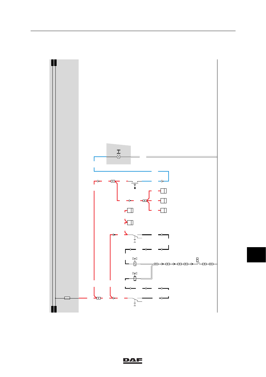
16. COMFORT CAB/SPACE CAB INTERIOR LIGHTING
The description of the interior lighting can be
divided into:
-
Stepwell lighting, driver’s side
-
Stepwell lighting, co-driver’s side
-
Interior lighting
-
Red interior nightlight
-
Interior bed lighting, driver’s side
-
Interior bed lighting, co-driver’s side
-
Bunk lamp
-
Storage compartment lighting
-
Map-reading lights
STEPWELL LIGHTING, DRIVER’S SIDE
If the driver’s side door is opened, switch E514
will close and the driver’s side stepwell lamp
(C062) will light up. A voltage is also applied
through wire 2600 to pin 17 of the CTE-2 unit
(D550). A voltage will also be applied internally
to connection point 27 of CTE-2 unit (D550),
causing the lamp of the driver’s side interior
lighting (C149) to light up.
If the driver’s side door is closed, a voltage will
be applied to connection point 27 of the CTE
unit for approx. 9 sec. This will result in a
delayed switching-off of the interior lighting. If a
speed signal is applied to pin 18, the delayed
switch off will not function.
The stepwell lighting is independent of the
contact switch position.
STEPWELL LIGHTING, CO-DRIVER’S SIDE
If the co-driver’s side door is opened, switch
E515 will close and the co-driver’s side stepwell
lamp (C063) will light up. A voltage is also
applied to C148 (interior lighting, co-driver’s
side) through wire 2609, diode D708 and wire
2633.
INTERIOR LIGHTING UNDERSIDE ROOF
CONSOLE
A voltage is applied to switch C151 (interior
lighting with middle switch) through fuse E030
and wire 1104. Depending on the switch
position, C151 (interior lighting underside roof
console) will light up.
10
ǹ 9711
Нет комментариевНе стесняйтесь поделиться с нами вашим ценным мнением.
Текст