DAF LF45, LF55 Series. Manual — part 644
©
200515
3-5
Inspection and adjustment
EXPLANATORY NOTES ON THE MAINTENANCE ACTIVITIES
ΛΦ45/55 series
5
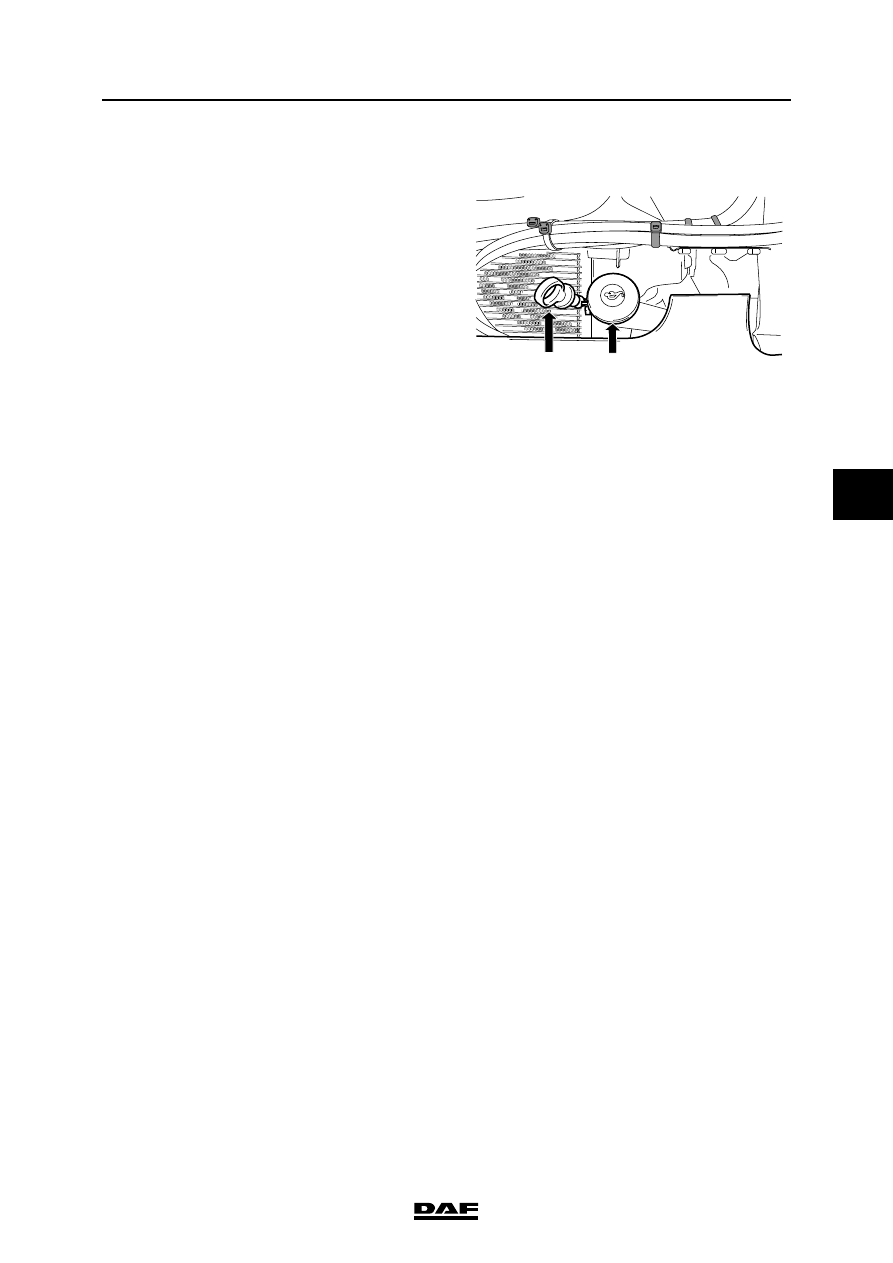
3.8 CHECKING THE ENGINE OIL LEVEL
1.
Ensure that the vehicle is entirely horizontal.
2.
Pull the dipstick (2) out of the holder.
3.
Wipe the dipstick clean with a lint-free cloth.
4.
Put the dipstick back into the holder.
5.
Pull the dipstick out again and check the oil
level.
Note:
It takes approx. 20 minutes for all the oil to
run into the sump when the engine is "warm".
If the dipstick is checked immediately after
switching the engine off or immediately after
oil has been added, the level shown on the
dipstick will be too low.
6.
Fill oil through the filler opening (1) until the
oil level reaches the maximum mark. See
"Draining and filling". Always use the
specified oil. Do not top up above maximum
level.
Note:
For the difference between minimum and
maximum engine oil level, see "Technical
data".
2
1
G0 00 212
EXPLANATORY NOTES ON THE MAINTENANCE ACTIVITIES
3-6
©
200515
Inspection and adjustment
5
ΛΦ45/55 series
3.9 CHECKING AND ADJUSTING BE ENGINE VALVE CLEARANCE
Note:
Checking and adjusting valve clearance must
only be done when the engine is cold.
1.
Remove the valve cover. See "Removing
and installing".
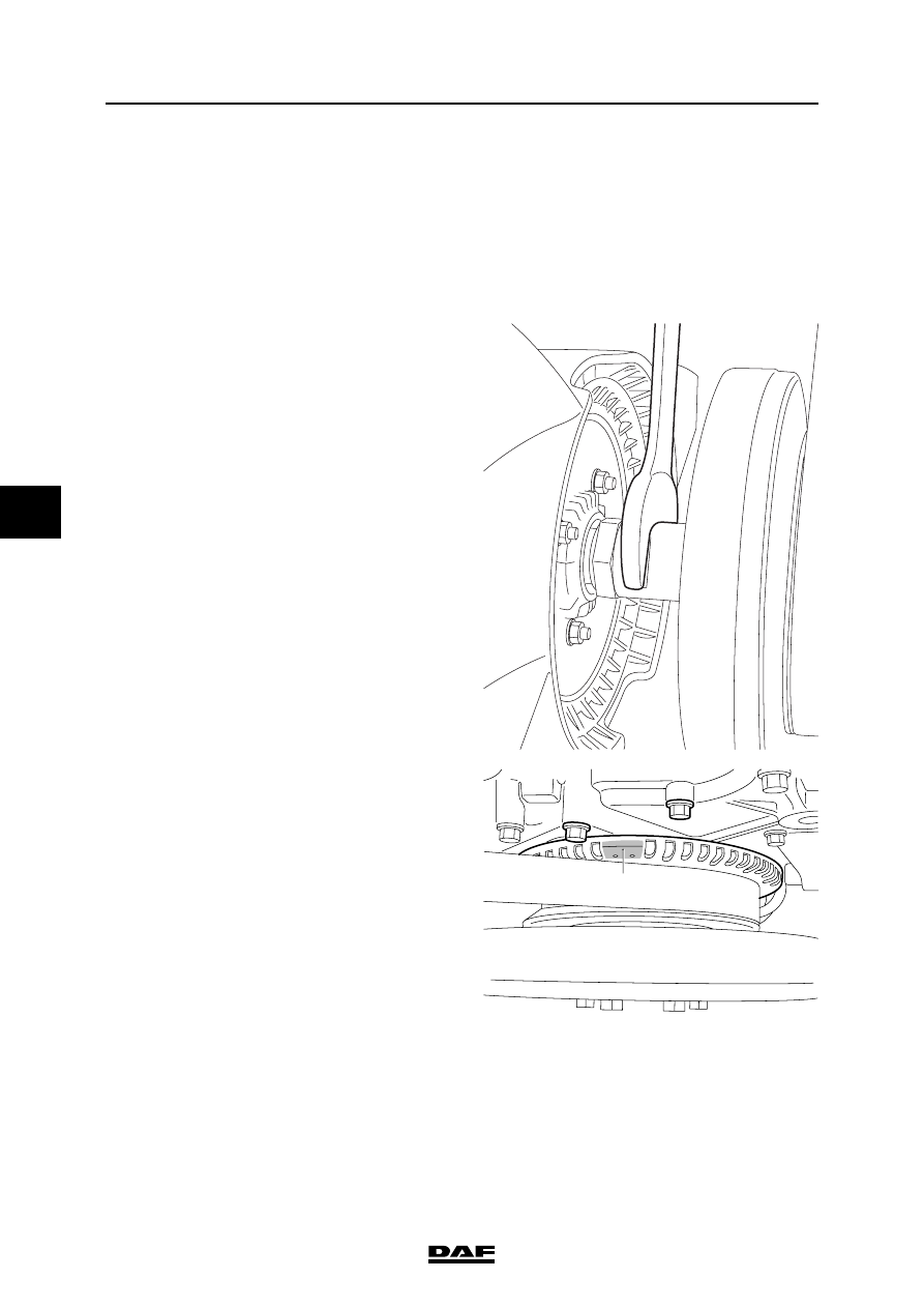
2.
Use an open-end spanner on the fan shaft to
turn the crankshaft clockwise, as seen from
the vibration damper end (this is the engine's
normal direction of rotation), until the mark
(A) is between the bolts (B) and the valves of
cylinder 1 are in overlap position.
Note:
"Overlap" is the moment at which the inlet
valves start opening and the exhaust valves
stop closing.
The inlet valves are operated by the short
rockers and the exhaust valves by the long
rockers.
M201318
M201065
A
B
B

©
200515
3-7
Inspection and adjustment
EXPLANATORY NOTES ON THE MAINTENANCE ACTIVITIES
ΛΦ45/55 series
5
3.
Check/correct the valve clearance of the
specified inlet and exhaust valves. Set the
correct valve clearance by loosening the lock
nut and rotating the adjusting screw in the
correct direction; see "Technical data" for the
correct valve clearance.
4.
Using an open-end spanner on the fan shaft,
turn the crankshaft one rotation further so
that the mark (A) is once again between the
bolts (B) and the valves of cylinder 4 overlap.
5.
Check/correct the valve clearance of the
specified inlet and exhaust valves. Set the
correct valve clearance by loosening the lock
nut and rotating the adjusting screw in the
correct direction; see "Technical data" for the
correct valve clearance.
6.
Fit the valve cover. See "Removing and
installing".
7.
Fit the flexible pipe, air inlet pipe and bracket.
M201064
Cylinder
Inlet valve
Exhaust valve
1
2
X
3
X
4
X
X
M201065
A
B
B
Cylinder
Inlet valve
Exhaust valve
1
X
X
2
X
3
X
4

EXPLANATORY NOTES ON THE MAINTENANCE ACTIVITIES
3-8
©
200515
Inspection and adjustment
5
ΛΦ45/55 series
3.10 INSPECTION AND ADJUSTMENT, CE ENGINE VALVE CLEARANCE
Note:
Inspection and adjustment of valve clearance
must only be carried out when the engine is cold.
1.
Remove the valve cover. See "Removal and
installation".
2.
Use an open-end spanner on the fan shaft to
turn the crankshaft clockwise, as seen from
the vibration damper end (this is the engine's
normal direction of rotation), until the mark
(A) is between the bolts (B) and the valves of
cylinder 1 are in overlap position.
Note:
"Overlap" is the moment at which the inlet
valves start opening and the exhaust valves
stop closing.
The inlet valves are operated by the short
rockers and the exhaust valves by the long
rockers.
M201318
M201065
A
B
B
Нет комментариевНе стесняйтесь поделиться с нами вашим ценным мнением.
Текст