DAF LF45, LF55 Series. Manual — part 404
29
1427090/03
EL001600
1
2
3
4
5
6
7
8
9
10
11
12
13
14
15
16
17
18
19
20
21
22
23
24
25
26
27
28
29
30
31
32
33
34
35
36
37
38
39
40
41
42
43
44
45
46
47
48
49
50
51
52
53
1000
2100
2100
2169
2169
2169
2169
1000
4953
4953
2169
4953
2169
2169
4953
2169
1104
1104
1104
2018
2018
2018
2018
2018
E349
1
2
2
4
1
C622
A13/702
A11/702
1/707
B4/703
4
722
3
722
2
815
2
814
1
815
1
814
C871
2
4
1
31
B129
M
2
31
B130
M
2
1
722
2
722
B7/701
D942
1010
1000
1010
1000
2101
2169
2100
E283
E163
10A
G000
3
1
24
5
M
20A
5
71
0I
C715
1
736
C145
1
2
C144
1
2
200440
2-105
5
ELECTRICAL SYSTEM
Electrical system
series
45/55
LF

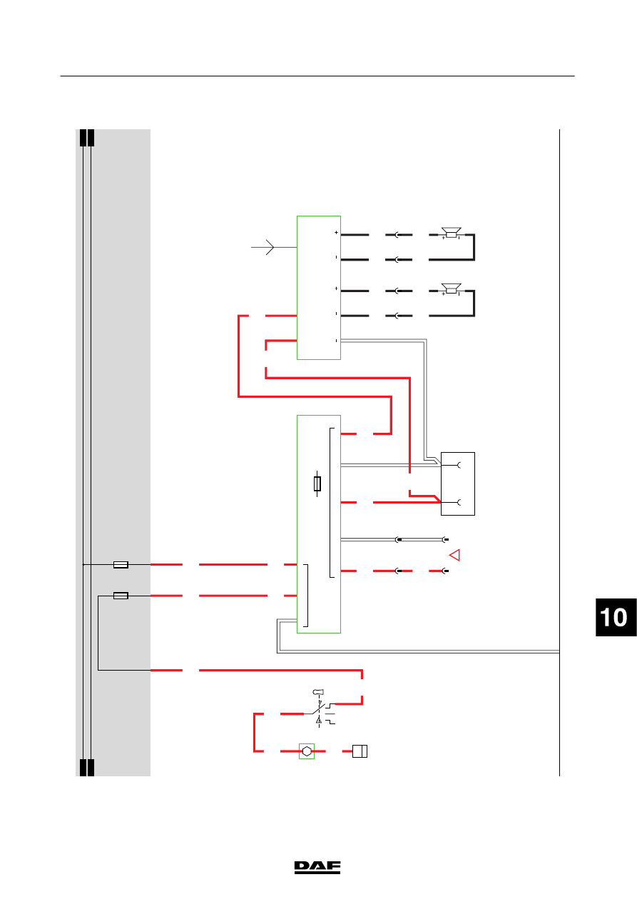
30.
24
V/12
V
C
ONVERTER
F
OR
RADIO
Note: The
following
description
of
the
operation
and
connection
is
intended
as
a
general
guideline
only
.
Also
refer
to
the
manufacturer
’s
installation
instructions
supplied
w
ith
the
radio.
The
converter
has
three
12
V
outputs.
-
P
in
4:
12
V
output
before
contact
-
P
in
6:
12
V
output
before
contact
-
P
in
9:
12
V
output
switched
via
accessories/ignition
switch
(C841)
If
the
contact
switch
(C841)
is
in
the
“accessories”
position
(connection
between
contacts
1
and
6),
the
converter
(D958)
is
supplied
w
ith
power
through
wire
1130
and
fuse
E026.
The
converter
receives
power
before
contact
at
pin
2
via
fuse
E027.
The
converter
has
an
internal
fuse
to
protect
the
12
V
outputs.
The
radio
has
an
aerial
connection
and
2
loudspeaker
outputs
w
hich
can
be
used
to
connect
loudspeakers
B
024
and
B025.
For
m
ore
information,
see
“Connection
of
accessories”.
VARIANTS
Location 19
Connector
790:
Optional
connector
for
,s
ay
,t
he
CB
or
CD
player
.
200440
2-106
5
ELECTRICAL SYSTEM
Electrical system
series
45/55
LF
30
1427090/03
EL001601
1
2
3
4
5
6
7
8
9
10
11
12
13
14
15
16
17
18
19
20
21
22
23
24
25
26
27
28
29
30
31
32
33
34
35
36
37
38
39
40
41
42
43
44
45
46
47
48
49
50
51
52
53
1130
1105
1130
1105
1160
1160
1108
4543
4541
4542
1153
4540
4543
4541
4542
4540
1000
1000
1000
1153
1108
1153
1153
1153
E349
1
2
B8/701
B9/701
A2/701
D942
1010
1000
1010
1000
E026
20A
E027
10A
1130
4
736
B025
2
736
6
736
B024
8
736
12V
B023
12V
L
L
R
R
4/784
7/784
3/785
4/785
5/785
6/785
8/784
4
774
3
774
2
790
1
790
A011
1
2
!
C841
1/808
2/808
4/808
6/808
7
65
49
3
24V
12V
12
D958
15A
200440
2-107
5
ELECTRICAL SYSTEM
Electrical system
series
45/55
LF
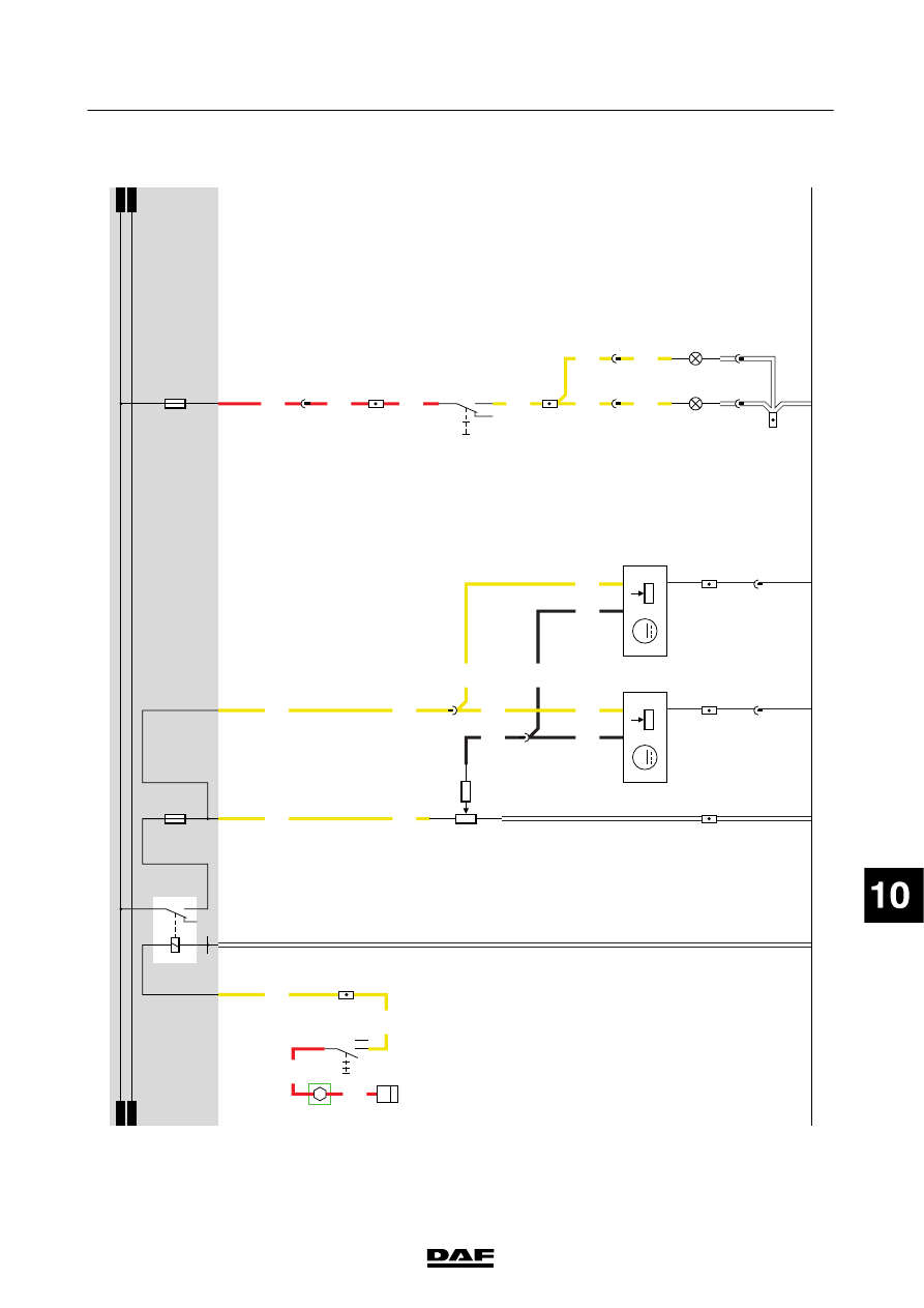
31.
CDS
-3
/DROP
G
LASS
OPERA
T
ION/ROOF
HA
TCH
DROP
G
LASS
OPERA
T
ION
When
the
vehicle
ignition
is
switched
on
(connection
between
pins
1
and
4,
C841),
relay
G
353
is
energised.
V
ia
fuse
E
044
and
wire
1208,
relay
G
353
supplies
power
to
the
electric
drop
glass
door
switches
(C864
in
the
co-driver
’s
door
,C
865
in
the
driver
’s
door
for
the
co-driver
’s
door
,and
C866
in
the
driver
’s
door). There
are
two
independent
drop
glass
switches.
In
the
rest
position,
pins
7
and
4
of
the
switch
are
connected
to
power
supply
via
wire
1208.
Depending
on
the
side
on
w
hich
the
switch
is
operated,
pin
7
or
4
will
be
connected
to
earth
and
the
drop
glass
motor
(B003
-
driver
’s
side,
B004
-
co-driver
’s
side)
will
be
activated.
200440
2-108
5
ELECTRICAL SYSTEM
Electrical system
series
45/55
LF
Нет комментариевНе стесняйтесь поделиться с нами вашим ценным мнением.
Текст