DAF LF45, LF55 Series. Manual — part 403
27C
1427090/03
EL001598
1
2
3
4
5
6
7
8
9
10
11
12
13
14
15
16
17
18
19
20
21
22
23
24
25
26
27
28
29
30
31
32
33
34
35
36
37
38
39
40
41
42
43
44
45
46
47
48
49
50
51
52
53
4001
1221
1221
1221
4001
4602
4602
4602
1221
4601
4601
1229
1229
3431
3432
3565
3566
4731
4731
4734
4734
1221
1000
1000
1000
4739
4739
4739
4753
4753
1221
1221
4753
4736
4736
4736
4735
1221
4753
E349
1
2
B1/702
4/712
8/707
2/712
A10/702
B10/702
A11/702
1
754
1
805
21/
340
20/
340
9/
340
33/
340
34/
340
7/
340
1/
340
8/
340
19/
340
27/
340
17/
340
16/
340
25/
340
5/
340
6/
340
D802
2
134
D529
754
4
754
3
12
903
2
754
2
723
10
903
3
723
9
903
2
903
13
903
2
904
2
805
11
903
1
904
1
903
1
723
F612
1
L
2
F615
F613
1
L
2
D942
1010
1000
1010
1000
E051
10A
E053
10A
1358
1221
4001
G353
3
1
24
5
M
E013
10A
E282
15A
1209
1356
G036
3
1
24
5
E587
4
12
D32/
746
D18/
746
D900
B10/
744
B9/
744
D20/
746
7/
755
D899
5/
755
C841
1/808
2/808
4/808
6/808
P
U
C742
4
62
0I
200440
2-101
5
ELECTRICAL SYSTEM
Electrical system
series
45/55
LF

200440
2-102
5
ELECTRICAL SYSTEM
Electrical system
series
45/55
LF
27C
1427090/03
EL001599
54
55
56
57
58
59
60
61
62
63
64
65
66
67
68
69
70
71
72
73
74
75
76
77
78
79
80
81
82
83
84
85
86
87
88
89
90
91
92
93
94
95
96
97
98
99
100
101
102
103
104
105
106
4741
4741
4741
4742
4742
4742
4740
4740
4740
4755
4755
4755
4754
4754
4754
4732
4732
4732
3514
3514
D942
1010
1000
1010
1000
4
903
5
723
5
903
4
723
3
903
6
723
8
903
8
723
7
903
7
723
4
B253
1
3
2
6
903
G520
B7/
753
B525
A021
7
13/
340
31/
340
15/
340
22/
340
4/
340
2/
340
30/
340
12/
340
D802
4
B254
3
1
200440
2-103
5
ELECTRICAL SYSTEM
Electrical system
series
45/55
LF
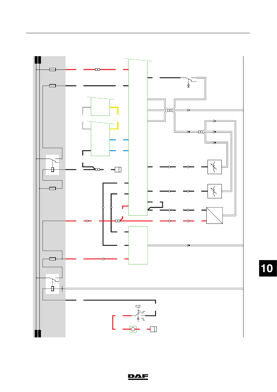
29.
HEADLAMP
H
EIGHT
ADJUSTMENT
/ROT
A
TING
BEAMS
HEADLAMP
H
EIGHT
ADJUSTMENT
Power
before
contact
is
supplied
at
pin
2
of
the
lighting
switch
(C622).
If
a
connection
is
made
to
switch
C622
(contacts
2
and
1),
a
voltage
is
applied
to
contact
1
of
relay
G
000
(tail
light/width
marker
light
relay)
via
w
ire
2100.
Once
the
relay
is
energised,
a
connection
is
made
between
points
3
and
5.
As
a
result,
a
voltage
is
applied
through
relay
G000
(contacts
3
-
5),
w
ire
2101,
fuse
E283
and
wire
2169
to
pin
2
of
switch
C
871
(potentiometer
for
headlamp
height
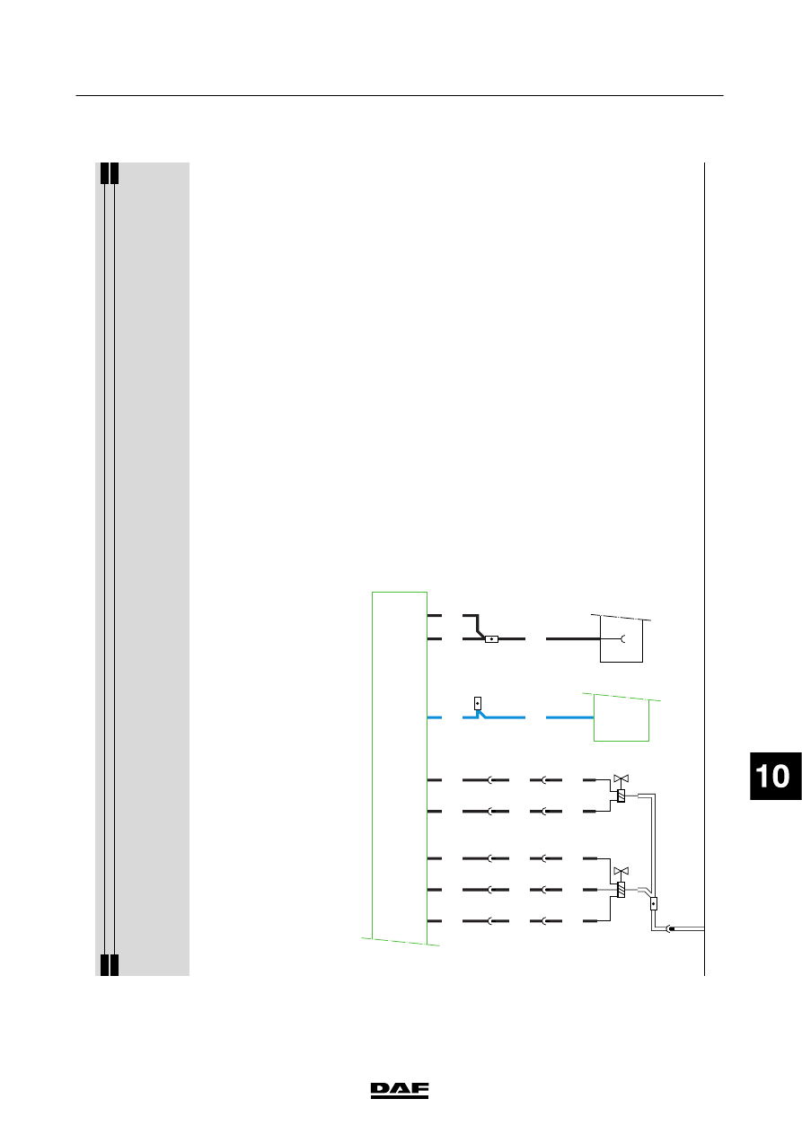
adjustment).
V
ia
the
same
wire,
power
is
also
supplied
to
pin
1
of
the
headlamp
height-adjustment
motor
on
the
left
(B129)
and
right
(B130).
When
the
headlamp
height
switch
is
operated,
the
voltage
at
pin
1
of
the
switch
will
change,
so
that
the
headlamp
height
adjustment
motors
on
the
left
(B129)
and
right
(B130)
will
be
activated
via
wire
4953
at
pin
3.
Depending
upon
the
position
of
C
871
(headlamp
height
adjustment
potentiometer),
the
m
otor
in
the
headlamp
w
ill
be
activated.
This
will
continue
until
electrical
equilibrium
is
achieved.
This
equilibrium
refers
to
the
voltage
dif
ference
that
exists
between
wires
2169
and
4953
of
C871,
B129
and
B130.
The
voltage
dif
ference
should
be
the
same
for
all
three
components.
ROT
A
TING
BEAMS
The
rotating
beam
switch
(C715)
is
supplied
with
power
before
contact
via
fuse
E163
and
wire
1104.
When
the
switch
is
operated,
rotating
beam
left
(C144)
and
rotating
beam
right
(C145)
will
be
supplied
w
ith
power
via
w
ire
2018.
200440
2-104
5
ELECTRICAL SYSTEM
Electrical system
series
45/55
LF
Нет комментариевНе стесняйтесь поделиться с нами вашим ценным мнением.
Текст