DAF LF45, LF55 Series. Manual — part 445
©
200436
2-1
Description of components
OPERATION OF BRAKE COMPONENTS
ΛΦ45/55 series
6
3
2. DESCRIPTION OF COMPONENTS
2.1 COMPRESSOR
The compressor is a 225-cm
3
one-cylinder
design with a water-cooled cylinder head. The
compressor is mounted on the left side of the
engine against the flywheel housing.
The compressor is driven by the camshaft gear
via a gear wheel.

OPERATION OF BRAKE COMPONENTS
2-2
©
200436
Description of components
3
ΛΦ45/55 series
6
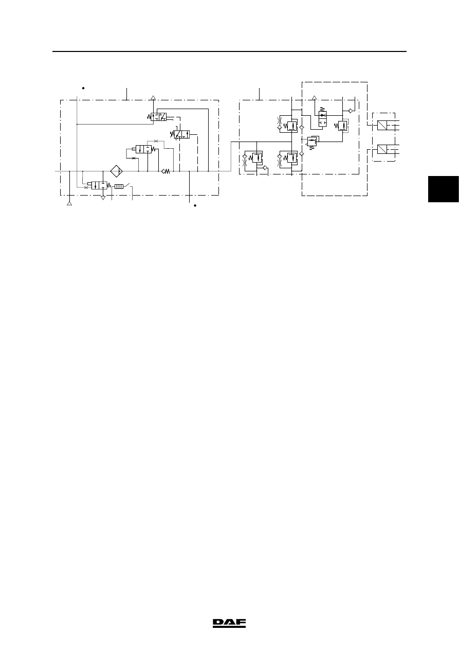
2.2 AIR SUPPLY UNIT
Purpose
The air supply unit is a combination of an air
dryer, pressure regulator and four-circuit safety
valve and has the following functions:
-
removing water, oil and other foreign matter
from the air before it enters the brake
system;
-
setting the system pressure by means of a
built-in pressure regulator;
-
limiting the pressure build-up to a given
value;
-
splitting the brake system into four circuits
and, should one circuit fail, protecting the
other circuits against running empty.
Air dryer function
Filling the system
The air supplied by the compressor reaches the
air dryer via connecting point 1/12. In the filter
element (1), the air passes through the coarse
filter (2), which sieves out the oil and dirt particles.
In addition, the air condenses against the cool
wall of the element. Subsequently, the air flows
through filter grains (3), which extract the water
vapour from the air. The air thus dried flows via a
non-return valve (4) to connecting point 21.
R600359
R600504
10
9
6
7
11
5
8
b
c
a
16
12
21
1/12
23
3
4
2
1
18
17
14
13
15
19
©
200436
2-3
Description of components
OPERATION OF BRAKE COMPONENTS
ΛΦ45/55 series
6
3
Operation, pressure regulator
The pressure increase occurring during filling is
returned to the built-in pressure regulator via
bore 12.
When the pre-set cut-out pressure is reached, the
control piston (13) is moved to the right against
the pressure of spring 14. This releases bore 15
in pin 16. The system pressure will enter space
"a" above blow-off valve 8 via bore 17, opening
the blow-off valve (8) against the pressure of the
spring (18).
If the pressure in the brake system drops to the
cut-in pressure due to air consumption, the
control piston (13) will move to the left and shut
bore 15 in pin 16. This bore, and therefore
channel 17 and space a, will now be bled via
bore 19. The blow-off valve (8) will close. The
compressor will now again build up the pressure
in the air system.
Regenerating
A regeneration tank is no longer necessary,
because the air inside the circuits is used.
A built-in pneumatic time switch controls the
regeneration process:
-
throttle 5 determines the amount of air;
-
throttle 6 determines the length of time.
24
21
1
F
D
H
K
3
A
E
C
G
1
12
24
26
22
21
23
3
23 25
P
U
6.2
6.3
6.4
6.1
6.2
P
U
6.5
6.6
6.7
B
R600580
0
OPERATION OF BRAKE COMPONENTS
2-4
©
200436
Description of components
3
ΛΦ45/55 series
6
Air is admitted to chamber "b" via throttle 6 and air
is also admitted to chamber "c" via bore 7 in the
piston (9). On cut-out by the pressure regulator,
the blow-off valve (8) is opened and chamber "c"
is bled via bore 7. The piston (9) is moved to the
right against the pressure of spring 10 as a result
of the difference in pressure between chambers
"b" and "c". This releases the piston (9) from its
seat (11) and air will flow in the opposite direction
via throttle 5 from the system through the filter
element. At the same time, pressure is reduced in
chamber "b" via throttle 6. The piston (9) moves
to the left until it abuts the seat (11). Regeneration
is now complete.
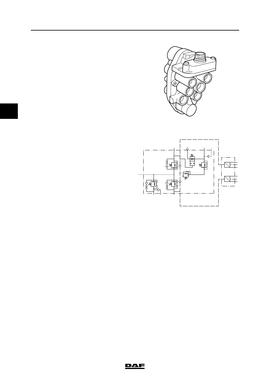
Four-circuit safety valve operation
The air supply enters via connecting point 1.
From there, the air flows to the built-in pressure
relief valves of circuits 1, 2 and 4.
As soon as the valve of circuit 1 and/or circuit 2
opens, the air will be able to flow through to
circuit 3, the trailer brake and parking brake
circuit. For reasons of safety, a built-in flowback
function empties circuit 3 when the pressure in
circuit 1 is too low. This is done to activate the
emergency brake function.
R600475
24
1
H
K
26
22
21
3
23 25
P
U
6.2
6.3
6.4
P
U
6.5
6.6
6.7
R600476
Нет комментариевНе стесняйтесь поделиться с нами вашим ценным мнением.
Текст