DAF LF45, LF55 Series. Manual — part 390
9
1427090/03
EL001569
1
2
3
4
5
6
7
8
9
10
11
12
13
14
15
16
17
18
19
20
21
22
23
24
25
26
27
28
29
30
31
32
33
34
35
36
37
38
39
40
41
42
43
44
45
46
47
48
49
50
51
52
53
1000
2100
2100
2170
2170
2170
2170
2170
2169
2170
2170
2170
2170
2170
2170
2169
2169
2169
2169
2169
2169
2169
2169
2169
2169
1000
E349
1
2
2
4
1
C622
A13/702
A4/703
A11/702
B10/703
3
736
1/710
D942
1010
1000
1010
1000
E283
10A
2101
2170
2100
E284
10A
G000
3
1
24
5
M
2169
A5/703
A10
713
6
762
1
809
A000
21
6
2
765
C022
1
2
C159
1
2
C158
1
2
C157
1
2
C156
1
2
A11
713
7
762
2
764
C023
1
2
12
762
4
722
3
722
6
721
G520
G520
1
765
2
809
1
764
!
!
1
810
G520
2
810
!
!
!
200440
2-49
5
ELECTRICAL SYSTEM
Electrical system
series
45/55
LF

10.
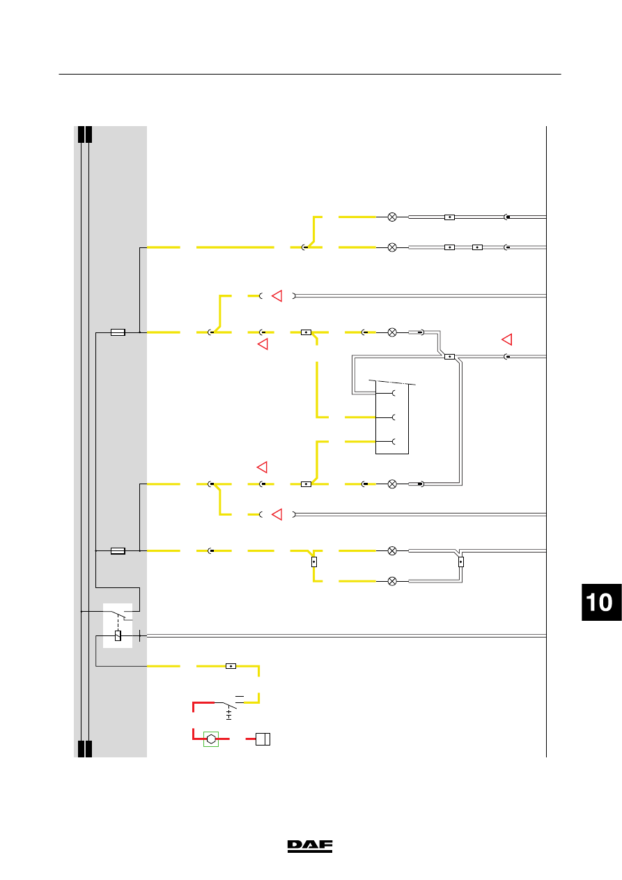
REVERSING
LIGHTS/BUZZER
When
the
contact
is
switched
on,
power
is
supplied
to
the
reversing
light
switch
(E501)
via
E
018
and
wire
1217.
This
switch
is
mounted
in
the
gearbox.
T
he
contacts
are
closed
w
hen
the
gearbox
is
switched
to
the
“reverse”
position.
Power
is
then
supplied
via
wire
4591
to
the
reversing
lights
(C026/C027)
and
drawn
vehicle
connector
A
001.
The
reversing
buzzer
(B176)
can
only
be
activated
via
wire
5104
if
the
dashboard
switch
(C880)
is
in
position
I.
S
witching
C880
to
the
0
position
turns
of
ft
he
reversing
buzzer
.
The
application
connector
(A070)
also
has
a
connection
that
is
switched
by
the
reversing
light
switch
(E501).
VARIANTS
Location 22,
27
Connector
762:
N
otf
itt
edo
nv
eh
ic
let
yp
eF
T
32
Connector
758:
N
otf
itt
edo
nv
eh
ic
let
yp
eF
T
200440
2-50
5
ELECTRICAL SYSTEM
Electrical system
series
45/55
LF

10
1427090/03
EL001570
1
2
3
4
5
6
7
8
9
10
11
12
13
14
15
16
17
18
19
20
21
22
23
24
25
26
27
28
29
30
31
32
33
34
35
36
37
38
39
40
41
42
43
44
45
46
47
48
49
50
51
52
53
4001
1217
4001
1217
4591
4591
4591
4591
5104
5104
5104
4591
4591
4591
4591
4591
4591
4591
1000
1000
1000
E349
1
2
B11/702
A10/702
D942
1010
1000
1010
1000
E018
15A
4001
A7
713
B2
713
1
762
1
758
A3
713
E501
2
1
A001
31
3
765
C026
1
2
3
764
C027
1
2
12
762
G520
2
758
G520
B176
1
2
5
71
0I
C880
1
765
1
764
C841
1/808
2/808
4/808
6/808
A070
4
!
!
!
!
200440
2-51
5
ELECTRICAL SYSTEM
Electrical system
series
45/55
LF
11
.
L
IGHTING/DIPPED
BEAM/MAIN
B
EA
M/SWEDISH
L
IGHTING/FOG
LAMPS
MARKER,
PARKING
AND
TA
IL
LIGHTS
FOR
SECTION
DIAGRAM
A
ND
EXPLANA
T
ION:
SEE
SECTION
DIAGRAM
9
LIGHT
S
WITCH
Position
1
(“town
lights”)
By
switching
the
lighting
switch
(C622)
to
the
1st
position
(connection
between
contacts
2
and
1),
relay
G000
is
activated
through
wire
2100.
Relay
G
000
provides
power
to
the
marker
lights
and
tail
lights
and
to
the
fog
lamps
switch
(C727),
pins
1
and
2.
This
is
done
via
fuse
E
285,
wire
2639.
There
is
also
a
connection
via
the
same
fuse
and
wire
to
the
V
IC
(pin
C7/745)
for
the
“light
on”
buzzer
(in
D
IP).
Position
2
(“dipped
b
eam”)
By
switching
the
lighting
switch
(C622)
to
the
2nd
position
(connection
between
contacts
2
and
4),
relay
G001
is
energised
through
wire
21
10.
Power
for
the
dipped
beam
headlights
(C000)
and
the
V
IC
is
supplied
via
fuse
E004
and
wire
21
14
through
pin
D
36/746.
Dipped
beam
C001
is
supplied
w
ith
power
via
fuse
E005
and
wire
21
13.
Diode
D609
ensures
that
relay
G
000
remains
activated
w
hen
the
light
switch
is
turned
to
position
2.
MAIN
BEAM
“S
ignalling
light”
Steering
column
switch
C
775
is
supplied
w
ith
power
before
contact
at
pin
B3.
T
his
power
supply
is
used
for
signalling.
During
signalling,
points
B
3
and
B4
are
connected
to
each
other
.T
his
is
a
spring-loaded
connection.
Relay
G
002
is
activated
via
wire
2120.
Relay
G002
supplies
power
to
the
m
ain
beam
headlights
(C002/C003)
via
fuse
E
006,
through-connection
G743
and
wire
2122.
Wire
2122
is
also
connected
to
pin
C6/745
of
the
VIC
and
the
spotlights
(C006/C007).
T
he
VIC
switches
on
the
“main
beam”
indicator
in
the
DIP
via
the
I-CAN.
Diode
D610
prevents
voltage
from
getting
to
relays
G000
and
G001
through
connection
A4
when
the
m
ain
beam
switch
is
pulled
back
further
during
signalling.
Otherwise
this
would
activate
all
the
other
lights
during
signalling.
“Main
b
eam”
When
the
m
ain
beam
headlights
are
switched
on,
points
A
4
and
B4
of
the
steering
column
switch
(C775)
are
connected
to
each
other
.
Pin
A
4
is
supplied
w
ith
power
via
diode
D610
when
light
switch
C622
is
turned
to
position
2.
Relay
G
002
is
then
again
energised
via
wire
2120,
as
a
result
of
w
hich
the
m
ain
beam
headlights
(C002/C003)
will
come
on.
SWEDISH
L
IGHTING
Swedish
lighting
is
provided
using
through-connection
G735.
When
the
vehicle
ignition
is
switched
on,
relays
G000
and
G001
are
directly
activated
via
fuse
E
282.
As
a
result,
the
dipped
beam
headlights
are
activated
and
the
fog
lamp
switch
(C727)
is
supplied
w
ith
power
.
Diodes
D784
and
D785
are
fixed
on
the
P
CB
of
the
fuse
box.
In
vehicles
that
do
not
have
Swedish
lighting,
diode
D784
prevents
relay
G001
from
being
activated
w
hen
the
light
switch
(C622)
is
in
position
I.
D
iode
D785
prevents
relay
G000
from
being
activated
when
the
light
switch
is
moved
to
position
II.
The
interior
lighting
w
ill
NOT
switch
of
fwhen
the
engine
is
started.
200440
2-52
5
ELECTRICAL SYSTEM
Electrical system
series
45/55
LF
Нет комментариевНе стесняйтесь поделиться с нами вашим ценным мнением.
Текст