DAF LF45, LF55 Series. Manual — part 391
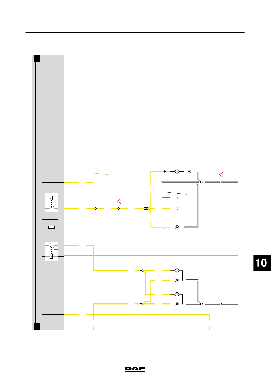
FRONT
F
OG
LIGHTS
Moving
the
fog
lamp
switch
(C727)
to
position
I(
fog
lamps,
front)
activates
relay
G
004
via
wire
2140,
provided
that
light
switch
C622
is
in
position
1.
R
elay
G004
supplies
the
front
fog
lamps
(C008/C009)
with
power
through
fuse
E009
and
wire
2142.
The
V
IC
(D900)
also
receives
power
through
wire
2140
at
pin
D34/746.
The
V
IC
switches
on
the
“front
fog
lamps”
indicator
on
the
instrument
panel
through
I-CAN.
REAR
FOG
L
IGHTS
When
the
fog
lamp
switch
(C727)
is
set
to
position
II,
which
is
spring-loaded,
the
V
IC
receives
a
voltage
signal
at
pin
D
35/746,
provided
that
light
switch
C622
is
in
position
1.
The
V
IC
then
activates
relay
G005
through
pin
C
40/745.
Relay
G
005
supplies
power
to
the
rear
fog
lamps
(C024/C025)
via
fuse
E009,
wire
2152.
If
the
lighting
or
the
ignition
has
been
turned
of
fand
the
lighting
is
then
turned
on
again,
the
fog
lamp
switch
(C727)
will
have
to
be
re-set
to
position
II
in
order
to
switch
on
the
rear
fog
lamps.
P
ow
eri
sa
ls
os
up
pl
ie
dt
od
ra
w
n
ve
hi
cl
e
connector
A
001
(pin
7)
via
w
ire
2152.
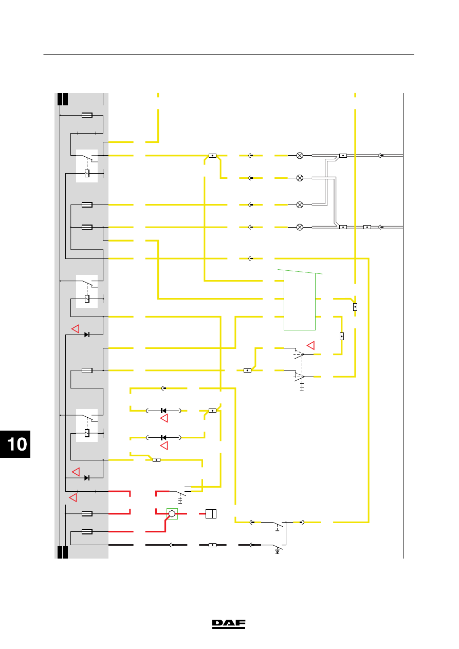
SPOTLIGHT Operating
the
main
beam
switch
(C775)
energises
m
ain
beam
relay
G
002
via
w
ire
2120.
Relay
G
002
supplies
power
to
the
spotlights
(C006/C007)
via
fuse
E
006
and
wire
2122.
VARIANTS
Location 9
R
emovable
through-connection
G735
for
S
wedish
lighting
(see
label
on
fuse
box)
11
T
hed
io
de
is
lo
ca
te
do
nP
C
B
D
49
2
15
Diode
located
in
diode
block
on
the
bottom
of
the
central
console
18
Diode
located
in
diode
block
on
the
bottom
of
the
central
console
24
If
only
a
rear
fog
light
is
fitted,
switch
C727
is
replaced
by
switch
C773.
26
The
diode
is
located
on
P
CB
D492
76,81
Connector
762:
N
otf
itt
edo
nv
eh
ic
let
yp
eF
T
200440
2-53
5
ELECTRICAL SYSTEM
Electrical system
series
45/55
LF
11
1427090/03
EL001571
1
2
3
4
5
6
7
8
9
10
11
12
13
14
15
16
17
18
19
20
21
22
23
24
25
26
27
28
29
30
31
32
33
34
35
36
37
38
39
40
41
42
43
44
45
46
47
48
49
50
51
52
53
1000
2100
2154
2100
2110
1000
4979
2639
2639
2639
2114
2113
2110
2114
2122
2120
2110
2110
2110
2100
2154
2140
2140
1000
4979
4979
1356
2120
2639
2639
2150
2150
2140
2140
2639
2114
2122
2114
2113
2122
2122
2122
2122
2122
2122
2140
2113
2114
2120
2120
2122
2154
E349
1
2
2
4
1
C622
A13/702
A6/703
B6/703
B12/701
B3/701
A9/701
A4/701
A1/703
A9/703
B2/703
B2/703
A3/701
A1/701
D609
D610
C775
A4
772
B3
772
2
741
2
741
9
798
7
798
1
721
3
741
4
722
3
722
B4
772
6
C727
3
21
0
l
ll
C7/
745
D36/
746
C6/
745
D900
D35/
746
D34/
746
B4/702
C000
1
2
2
721
C001
1
2
A8/701
4
721
C003
1
2
3
721
C002
1
2
!
2
798
4
798
!
!
D942
1000
1010
1010
1000
E285
10A
E005
10A
2101
4979
2100
2148
E282
15A
G000
3
1
24
5
2639
2148
2122
M
E019
15A
2
1
G735
3
4
G743
D784
2112
2114
2121
2110
G001
3
1
24
5
M
E006
15A
E004
10A
G002
3
1
24
5
MM
D785
2120
!
!
!
200440
2-54
5
ELECTRICAL SYSTEM
Electrical system
series
45/55
LF
11
1427090/03
EL001572
54
55
56
57
58
59
60
61
62
63
64
65
66
67
68
69
70
71
72
73
74
75
76
77
78
79
80
81
82
83
84
85
86
87
88
89
90
91
92
93
94
95
96
97
98
99
100
101
102
103
104
105
106
2122
2140
2140
2142
2152
2168
2122
2142
2122
2122
2142
2152
2152
2152
2152
2152
2142
6/711
7/711
A3/703
A3/702
A11/702
5
722
3
C006
C008
12
3
C007
C009
12
7
722
6
722
C40/
745
D900
5
762
A12
713
A001
71
6
765
C024
1
2
6
764
C025
1
2
12
762
G520
1
765
1
764
D942
1010
1000
1010
1000
2141
2141
E009
15A
2168
G004
3
1
24
5
G005
3
4
5
1
2
M
M
2140
!
!
200440
2-55
5
ELECTRICAL SYSTEM
Electrical system
series
45/55
LF
12.
ST
OP
LIGHTS/CAB
TIL
T
ING
G
EAR
ST
OP
LIGHTS
When
stop
light/clutch
operating
switch
E
587
is
operated
(connection
between
contacts
4
and
3)
by
depressing
the
brake
pedal,
relay
G036
is
energised
via
wire
4602.
Power
w
ill
also
be
supplied
to
the
VIC
(pin
D
32/746).
Through
fuse
E013,
wire
1209,
contacts
3
and
5
of
relay
G036
and
wire
4601
a
voltage
is
now
applied
to
the
right
stop
light
(C021)
and
the
left
stop
light
(C020),
so
that
they
come
on.
The
lights
that
are
connected
via
drawn
vehicle
socket
A
000
will
also
come
on.
The
ECAS-3
unit
(D851)
or
ECAS-2
unit
(D802)
then
also
receives
a
signal.
Application
connector
A
070
is
also
connected
to
wire
4601.
CAB
TIL
T
ING
G
EAR
The
switch
for
the
cab
lock
(F009)
is
a
“normally
closed”
switch.
T
he
switch
is
opened
when
the
cab
is
in
the
driving
position.
When
the
cab
is
tilted,
the
switch
closes
and
pin
B
16/744
of
the
V
IC
is
connected
to
earth
via
w
ire
4312.
When
the
alarm
is
active
it
knows
that
the
cab
is
in
the
driving
position
because
a
small
current
goes
to
earth
through
the
control
switch
for
cab
tilting
(F009).
D
iode
D758
prevents
this
current
from
also
flowing
to
earth
through
the
V
IC
(the
VIC
in
sleep
mode),
in
which
case
the
alarm
w
ould
not
know
whether
the
cab
is
being
tilted
intentionally
or
by
accident.
VARIANTS
Location 23,28
Connector
762:
N
otf
itt
edo
nv
eh
ic
let
yp
eF
T
29
Electronic
unit,
ECAS-3
(D851):
On
a
6x2
vehicle,
E
C
A
S
-2
electronic
unit
D
802
(7/340)
200440
2-56
5
ELECTRICAL SYSTEM
Electrical system
series
45/55
LF
Нет комментариевНе стесняйтесь поделиться с нами вашим ценным мнением.
Текст