DAF LF45, LF55 Series. Manual — part 425

11
15
1427090/04
EL001631
1
2
3
4
5
6
7
8
9
10
11
12
13
14
15
16
17
18
19
20
21
22
23
24
25
26
27
28
29
30
31
32
33
34
35
36
37
38
39
40
41
42
43
44
45
46
47
48
49
50
51
52
53
4001
1208
1208
1208
1208
4001
1000
1603
4532
4530
4532
4532
4532
4532
4532
4532
4771
4771
4771
4773
4773
4773
4774
4774
4771
4773
4774
4774
4770
4772
4772
4770
4774
4774
4770
4773
4774
4771
4772
4774
1208
1208
1208
1208
4532
4532
4532
1603
1000
1000
1000
1000
A10/702
A11/702
6/709
10
738
1
789
2
732
11
738
4
733
G397
87
30
87A
85
86
t=12m
B371
2
1
B018
2
1
1
788
9
739
9
738
2
789
2
788
6
789
14
738
4
789
12
738
5
789
5
788
4
788
6
788
14
739
12
739
13
739
13
738
B017
2
1
5
71
0I
C867
9
31
0
8
4
75
C868
B006
M
M
65
4
B005
M
M
4
56
D942
1010
1000
1010
1000
1358
E044
20A
G353
3
1
24
5
4001
M
739
10
C841
1/808
2/808
4/808
6/808
A500
E349
80A
2
1
E299
50A
2
1
G507
G507
G507
50
30
B010
M
31
200440
2-41
Changes in the electrical system from chassis number 0L247507
5
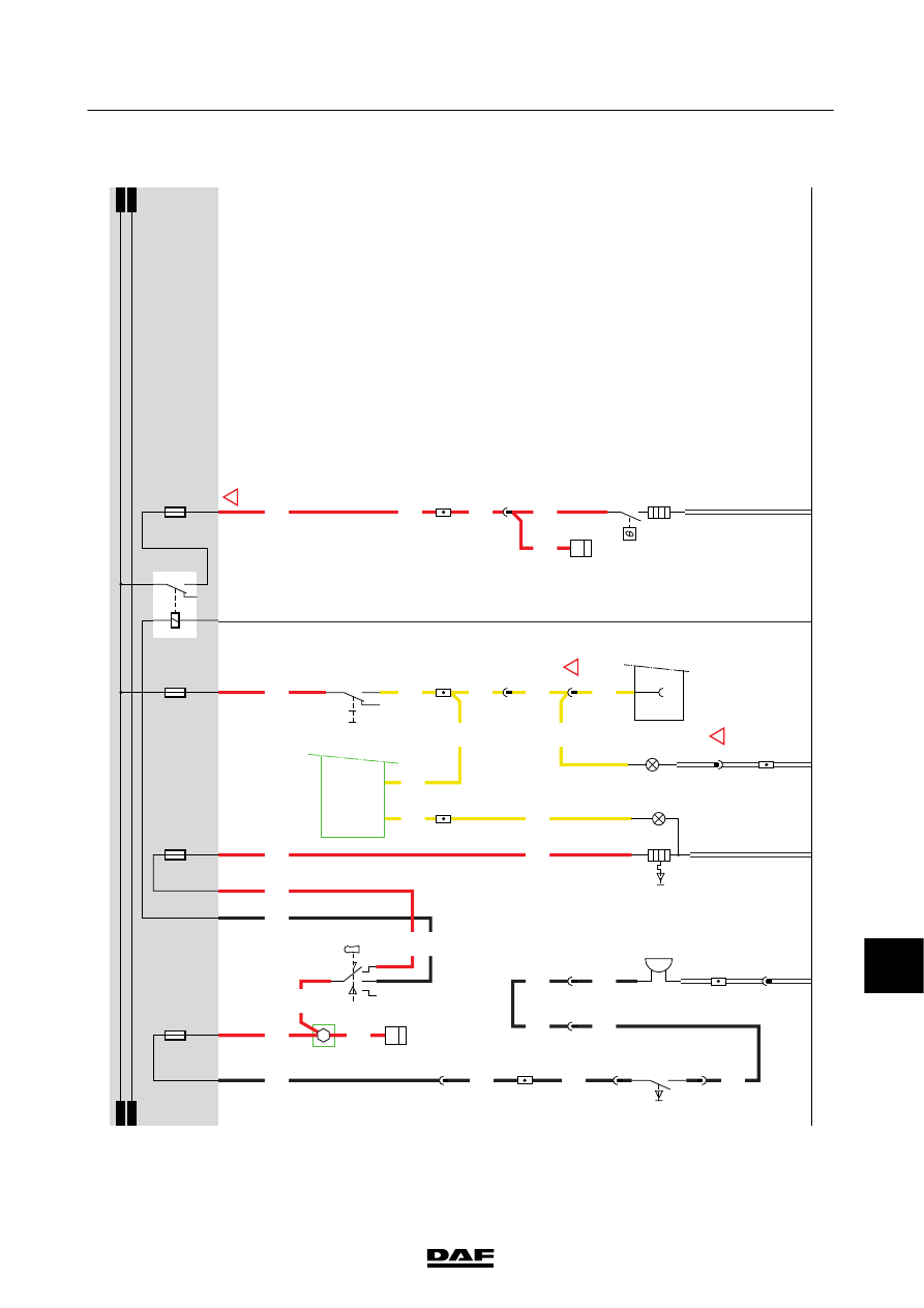
CHANGES IN THE ELECTRICAL SYSTEM
LF45/55 series
11
19.
HORN/CIGAR
L
IGHTER/WORK
LAMP/AIR
DR
YER
HORN The
horn
(B401)
is
activated
before
contact
via
steering
column
switch
C
775
(1000).
T
he
horn
is
supplied
w
ith
power
via
w
ire
4979
and
fuse
E019.
CIGAR
L
IGHTER
If
the
vehicle
ignition
switch
(C841)
is
in
the
“accessories”
position
(connection
between
contacts
1
and
6),
cigar
lighter
B030
is
supplied
w
ith
power
via
fuse
E
026
and
wire
1105.
By
depressing
the
cigar
lighter
,t
he
heating
element
is
warmed
up.
WORK
LAMP
W
ork
lamp
switch
C725
is
supplied
w
ith
voltage
from
power
supply
before
contact
and
via
fuse
E
052.
When
the
switch
is
operated
voltage
is
applied
to
the
work
lamp
(C071)
and
to
pin
C
9/745
of
the
V
IC
unit
in
order
to
ac
tiv
ate
the
“work
lamp”
indic
ator
on
the
DIP
via
I-CA
N
.
AIR
D
R
YER
When
the
vehicle
ignition
(C841)
is
on
(connection
between
contacts
1
and
4),
relay
G353
is
activated.
This
relay
supplies
power
to
the
air
dryer
heating
element
(B042)
via
fuse
E091
and
wire
1240.
When
the
m
aximum
temperature
is
reached,
a
thermal
switch
in
the
air
dryer
switches
of
f.
The
w
ater
separator
sensor
(F692)
is
supplied
with
power
via
the
same
wire.
VARIANTS
Location 20,24
Connector
780:
N
otf
itt
edo
nv
eh
ic
let
yp
eF
A
.
Wire
2155
only
fitted
in
application
connector
A
070
35
If
the
vehic
le
is
fitted
w
ith
CDM,
see
section
diagram
32
200440
2-42
5
CHANGES IN THE ELECTRICAL SYSTEM
Changes in the electrical system from chassis number 0L247507
LF45/55 series
11
19
1427090/04
EL001632
1
2
3
4
5
6
7
8
9
10
11
12
13
14
15
16
17
18
19
20
21
22
23
24
25
26
27
28
29
30
31
32
33
34
35
36
37
38
39
40
41
42
43
44
45
46
47
48
49
50
51
52
53
1130
4001
1240
1130
1105
1110
4001
4535
4535
1000
1000
4979
1000
4979
2155
1240
2155
2155
1240
1240
2622
2155
2155
2155
2155
1240
4979
4535
4535
2622
1105
4535
E349
1
2
7/707
4/710
A2/701
A10/701
A10/702
A11/702
A3/701
A1/701
D942
1010
1000
1010
1000
E091
10A
E052
10A
E019
15A
E026
20A
1358
1130
4979
4001
G353
3
1
24
5
M
4
741
B12
713
B4
713
2
742
5
721
4
722
C775
B2
772
B5
772
D900
C9/
745
C49/
745
C725
5
71
0I
B042
2
1
G520
G520
F692
3
39
B030
31
12
C841
1/808
2/808
4/808
6/808
B401
2
1
A070
2
1
780
C071
1
2
2
780
!
!
!
200440
2-43
Changes in the electrical system from chassis number 0L247507
5
CHANGES IN THE ELECTRICAL SYSTEM
LF45/55 series
11
22.
ECS
-DC3/EXHAUST
BRAKE
FOR
M
ORE
INFORMA
TION
SEE
SYSTEM
MANUAL
VARIANTS
Location 49
Connector
852:
Optional
connector
for
“remote
throttle”
func
tion
66
The
C
AN
terminating
resistor
is
fitted
in
the
wiring
harness,
near
the
B
connector
129
This
part
of
the
ECS-DC3
electronic
unit
relates
to
the
BE
engine
(4-cylinder)
186
This
part
of
the
ECS-DC3
electronic
unit
relates
to
the
CE
engine
(6-cylinder)
200440
2-44
5
CHANGES IN THE ELECTRICAL SYSTEM
Changes in the electrical system from chassis number 0L247507
LF45/55 series
Нет комментариевНе стесняйтесь поделиться с нами вашим ценным мнением.
Текст