DAF LF45, LF55 Series. Manual — part 179
©
200505
4-3
Checking and adjusting
BE ENGINE COOLING SYSTEM
ΛΦ45/55 series
2
3
4.3 INSPECTION, VISCOUS FAN CLUTCH
Do not run the engine in an enclosed
or unventilated area. Make sure
exhaust fumes are properly
extracted. Remain at a safe distance
from rotating and/or moving
components.
Testing with a cold engine
During this test, the slip in the viscous fan clutch
is measured while the clutch is not operating.
This test must be carried out when the engine is
"cold" (coolant temperature approximately 50
C).
1.
Check the coolant level, and top up as
necessary.
2.
Start the engine and run it at idling speed for
at least 5 minutes.
Then use an optical rev counter to measure
the fan speed at different engine speeds
(from idling to maximum engine speed).
During this test procedure, the speed of the
fan should be approx. 600 to 1100 rpm.
Testing with a warm engine
This test checks whether the bimetallic strip starts
opening the valve at an operating temperature of
85 - 95
C.
1.
Check the coolant level, and top up as
necessary. Be careful when topping up the
coolant of a warm engine.
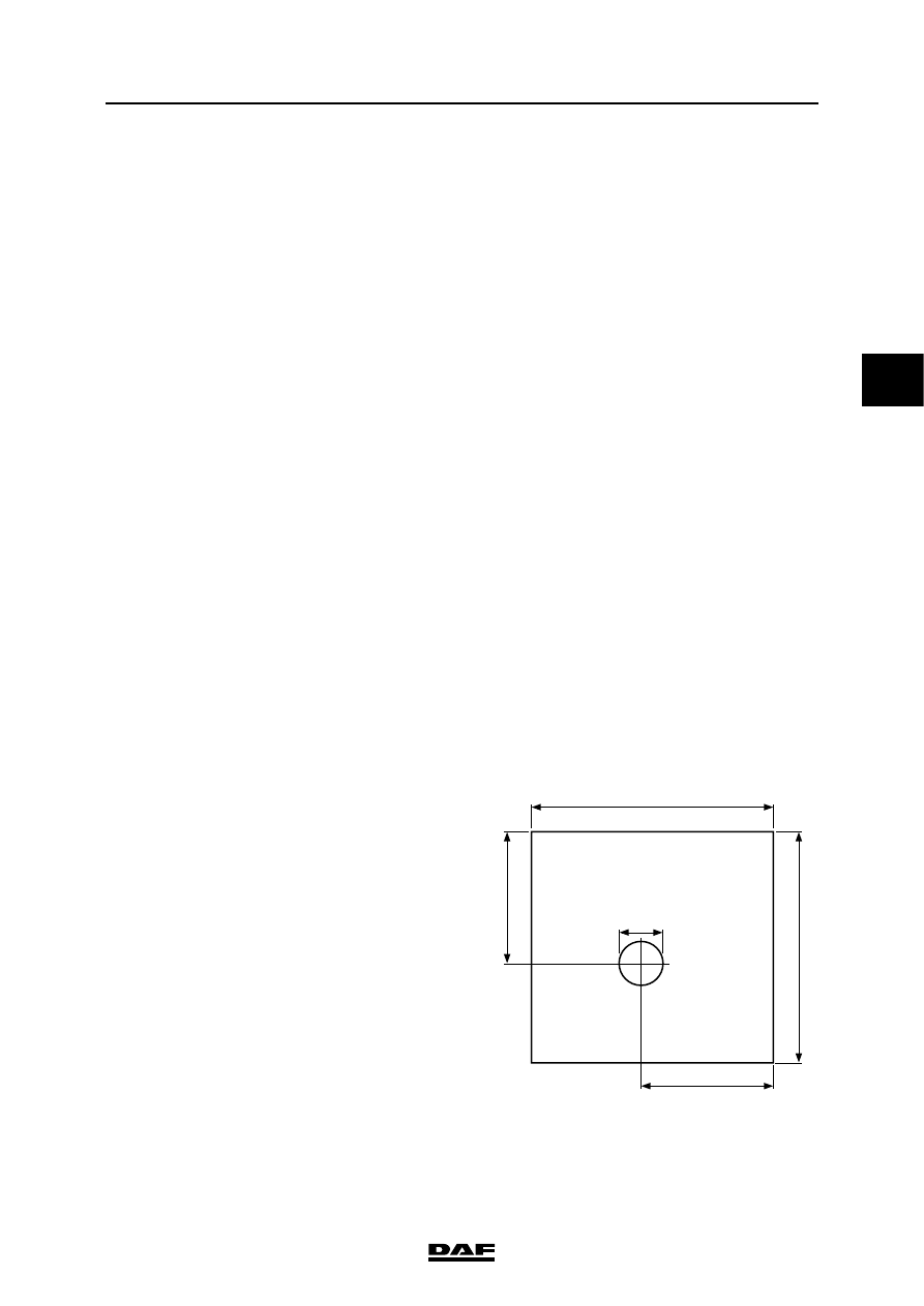
2.
Take a sheet of cardboard with a 100 mm
hole, as shown in the drawing opposite, and
place it in front of the radiator, with the hole
in front of the viscous clutch.
3.
Check that the gearbox is in neutral.
4.
Bring the cooling system to operating
temperature.
5.
Allow the fan drive flange to run at a speed of
1000 rpm. Then use an optical rev counter to
determine the difference between the
rotating speeds of the fan and the drive
flange. The speeds will differ as a result of
slip in the viscous clutch. When the clutch is
fully engaged, the slip must not exceed 10%.
If it is more, the viscous fan clutch must be
replaced.
}
100
550
300
525
300
M201167
BE ENGINE COOLING SYSTEM
4-4
©
200505
Checking and adjusting
3
ΛΦ45/55 series
2
©
200505
5-1
Removing and installing
BE ENGINE COOLING SYSTEM
ΛΦ45/55 series
2
3
5. REMOVING AND INSTALLING
5.1 REMOVAL AND INSTALLATION, COOLANT PUMP
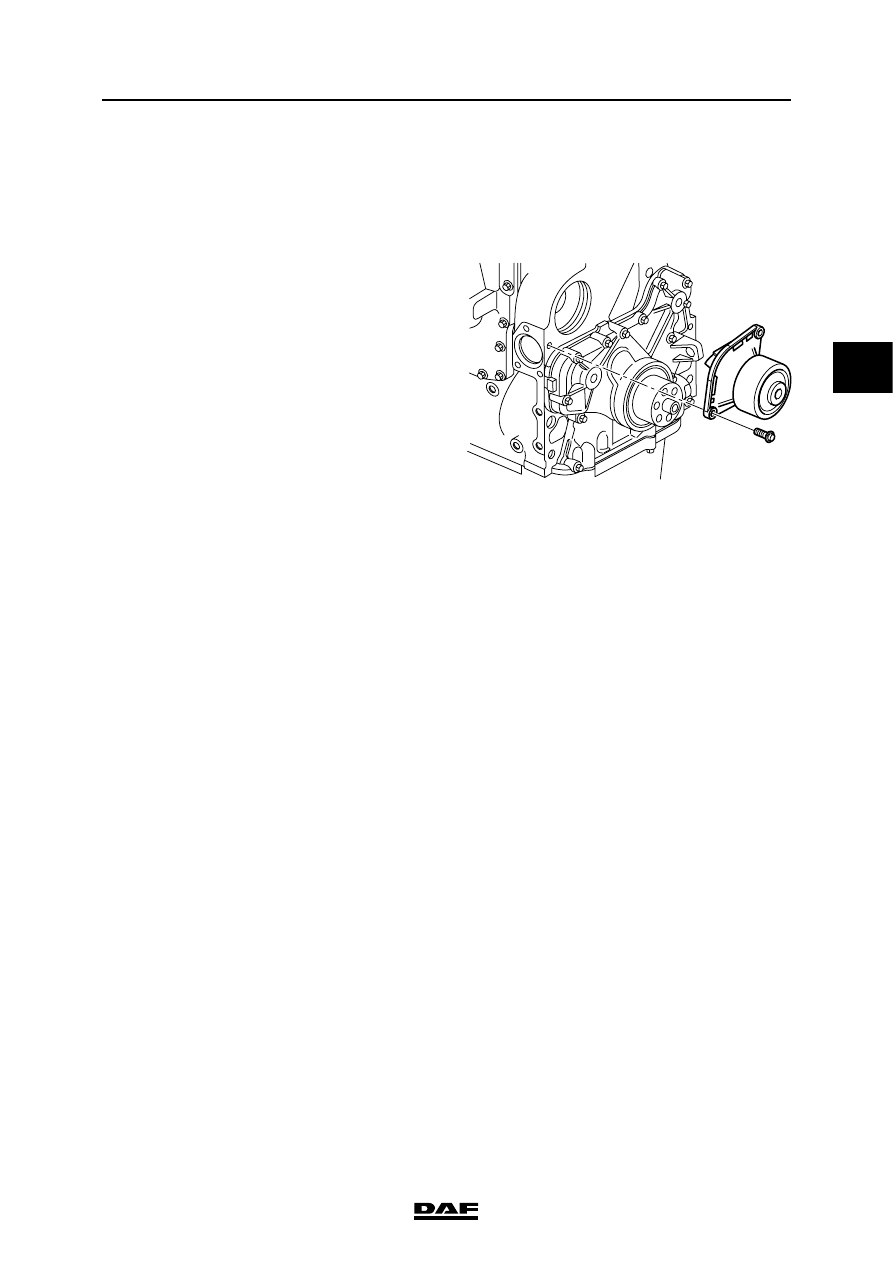
Removing the coolant pump
1.
Drain the coolant. See "Draining and filling".
2.
Remove the poly-V-belt.
3.
Remove the attachment bolts from the
coolant pump and remove it.
Installing the coolant pump
1.
Thoroughly clean the sealing surfaces of the
coolant pump and the cylinder block.
2.
Fit a new O-ring to the coolant pump.
3.
Install the coolant pump and tighten the
attachment bolts to the specified torque. See
"Technical data".
4.
Fit the poly-V-belt.
5.
Fill the cooling system. See "Draining and
filling".
M201137
BE ENGINE COOLING SYSTEM
5-2
©
200505
Removing and installing
3
ΛΦ45/55 series
2
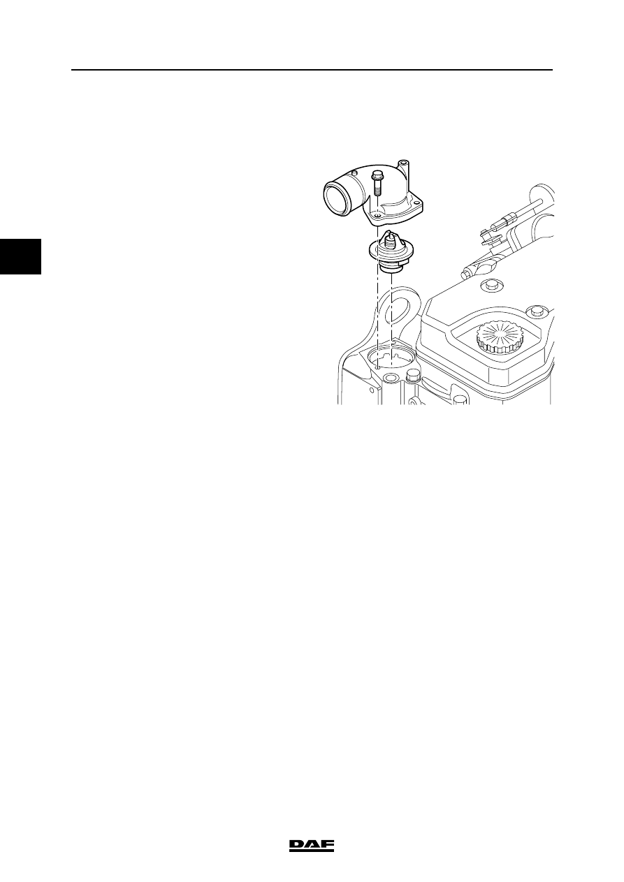
5.2 REMOVAL AND INSTALLATION, THERMOSTAT
Removing the thermostat
1.
Drain the coolant. See "Draining and filling".
2.
Remove the water hose between the
thermostat housing and the radiator.
3.
Remove the thermostat housing attachment
bolts.
4.
Remove the thermostat housing.
5.
Remove the thermostat.
Installing the thermostat
1.
Fit a new sealing ring to the thermostat.
2.
Fit the thermostat in the thermostat housing.
3.
Fit the thermostat housing onto the cylinder
head.
4.
Fit the thermostat housing attachment bolts.
Tighten the attachment bolts to the specified
torque. See 'Technical data'.
5.
Fit the water hose between the thermostat
housing and the radiator.
6.
Fill the cooling system. See "Draining and
filling".
M201156
Нет комментариевНе стесняйтесь поделиться с нами вашим ценным мнением.
Текст