DAF LF45, LF55 Series. Manual — part 357
5
LF45/55 series
List of abbreviations
READING DIAGRAMS
1-1
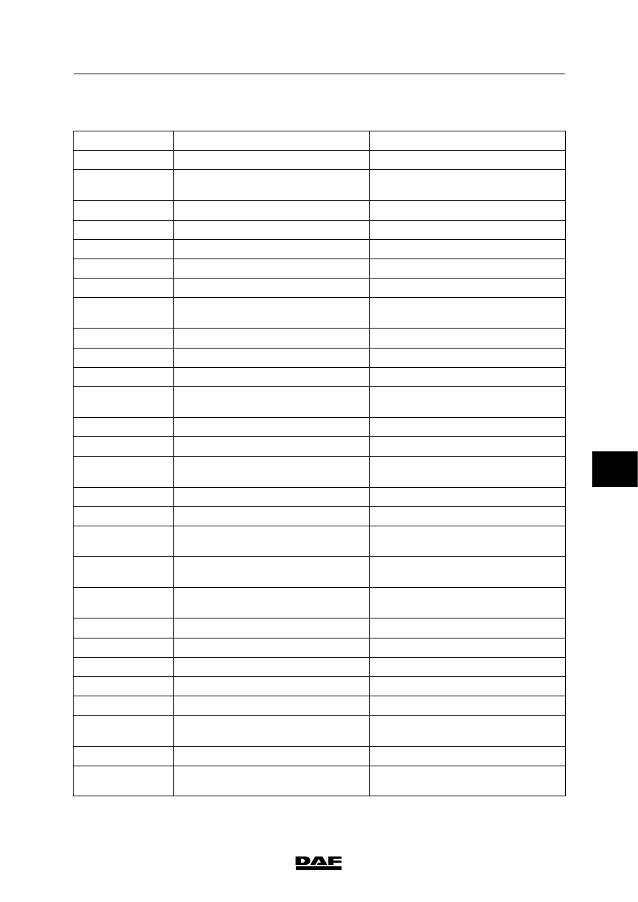
1. LIST OF ABBREVIATIONS
Abbreviation
Explanation
Translation/description
ABS-D
Antilock Braking System - version D
Antilock braking system - version D
ABS/ASR-E
Antilock Braking System/Anti-Slip
Regulation - version E
Antilock braking system/Anti-slip
regulation - version E
ACH-W
Additional Cab Heater - Webasto
Cab heater - Webasto
AGC-A
Automatic Gearbox Control - Allison
Automatic Allison gearbox control
AIRCO
Air conditioning
Air conditioning
ALS-S
Alarm system - Scorpion
Alarm system - Scorpion
ASR
Anti-Slip Regulation
Anti-slip regulation
CAN
Controller Area Network
Multiplex digital communication
network
CCU
CAN Connection Unit
CAN connection unit
CDB
Central Distribution Board
Central box
CDM
CAN Data Manager
CAN Data Manager
CDS-3
Central Door Locking System
version 3
Central door locking system -
version 3
CO
Change Over
Changeover contact
CXB
CAN extension box
CAN extension box
DAVIE XD
DAF Vehicle Investigation
Equipment - version XD
DAF vehicle diagnostic tool -
version XD
DIP-4
DAF Instrument Pack - version 4
DAF instrument panel - version 4
DVB
DoorVerBinding
Through-connection
ECAS-2
Electronically Controlled Air
Suspension system - version 2
Electronically controlled air
suspension system - version 2
ECAS-3
Electronically Controlled Air
Suspension system - version 3
Electronically controlled air
suspension system - version 3
ECS-DC3
Engine Control System DAF
Cummins - version 3
DAF Cummins engine management
system - version 3
FMS
Fleet Management System
Fleet Management System
MTCO
Modular Tachograph
Modular tachograph
NC
Normally Closed
Normally closed contact
NO
Normally Open
Normally open contact
PTO
Power Take-Off
Power take-off
RAS-EC
Rear Axle Steering - Electronically
Controlled
Electronically controlled rear axle
steering
VIC
Vehicle Intelligence Centre
Vehicle intelligence centre
VLG/ADR/GGVS/
PETREG/RTMDR
Vervoer te Land Gevaarlijke Stoffen
Transport of hazardous substances
7
200440
5
READING DIAGRAMS
List of abbreviations
LF45/55 series
1-2
200440
7
5
LF45/55 series
Marking of wiring
READING DIAGRAMS
2-1
2. MARKING OF WIRING
INTRODUCTION
This standard sets out specifications for the
uniform use of markings on electrical wiring.
The marking system consists of a numerical
system and a colour coding system, thus
ensuring a clear wiring layout and precluding
faulty connections and manufacturing errors.
The marking system does not apply to vehicles
subject to special conditions, such as military
vehicles.
Numerical and colour coding
Each numerical code consists of four digits, the
first of which refers to the main group and to the
colour.
Main groups
Power supplies (red)
1000 to 1999
Lighting (yellow)
2000 to 2999
Warning and control functions (blue)
3000 to 3999
Power consumers (grey)
4000 to 6999
Special applications (colour as desired)
6000 to 6999
Earth connections (white)
Not marked
9000 to 9499 test and signal earth
I-CAN wiring (twisted)
3565 CAN-L (yellow)
3566 CAN-H (grey)
V-CAN wiring (twisted)
3700 CAN-L (yellow)
3701 CAN-H (blue)
Notes:
-
The “M” with serial number coding on earth
wiring is used for production-related
reasons.
-
In the case of straight splicing of the wiring
(cascading), the numerical codes are shown
on each separate wire followed by a serial
letter.
7
200440

5
READING DIAGRAMS
Marking of wiring
LF45/55 series
2-2
Earth connections
The application of electronic systems has made
it necessary to divide the earth connections into
groups. There is a distinction to be made
between two different types of earth connection:
-
switching earth
-
test and signal earth
The switching earth is the conventional type of
earth.
The test and signal earth is used exclusively for
electronic systems.
The wiring colour for both types of earth is white,
but the test and signal earth wiring is marked
with numerical codes (from 9000 to 9500).
NEVER USE THE TEST AND
SIGNAL EARTH WHEN FITTING AN
ELECTRICAL COMPONENT
If you do this, electronic components may not
work correctly.
If an electronic component needs to be
connected, the earth for this system must be
connected to the central earth connection in the
cab.
This connecting point is located under the
central box behind the dashboard.
Abbreviations used in colour coding
Colour
Abbre-
viation
Colour
Abbre-
viation
red
rd
yellow
gl
brown
bn
white
wt
green
gn
grey
gs
blue
bw
black
zt
orange
oe
violet
vi
pink
re
200440
7
Нет комментариевНе стесняйтесь поделиться с нами вашим ценным мнением.
Текст