DAF LF45, LF55 Series. Manual — part 358
5
LF45/55 series
Reading circuit diagrams
READING DIAGRAMS
3-1
3. READING CIRCUIT DIAGRAMS
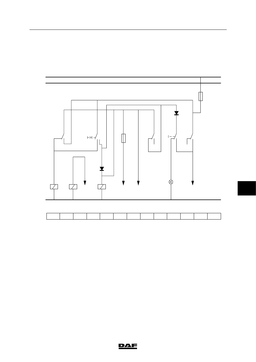
The circuit diagram is intended to show the
various circuits in the simplest way possible.
Symbols are used to do this.
58
59
60
61
62
63
64
65
66
67
68
69
70
1000
1010
M
LIGHT SWITCH
SWITCH MAIN/ DIPPED BEAM
G107
C622
1101
5.0A
D609
G000
85
86
G107
85
86
G154
85
86
E002
1020
2105
2630
2110
2100
2111
2120
E084
2154
59 30
2
2
1
1
2
7.5A
1
2
4
1
87
G154
C506
D610
58
30
87
143
205
251
009
039
052
146
LAMP
MAIN
SWITCH
NO
68
CO
59
NC
65
87A
87A
G000
61
30
3.4
2
1
87
3.5
87A
E501056
1. In the diagram, the indications “1000” and
“1010” are shown at the top, left side.
Explanation to these indications:
1000 = power supply before contact.
1010 = power supply after contact.
2. The indication “M” is shown at the bottom of
the diagram, left side.
Explanation to this indication:
M = earth connection.
7
200440
5
READING DIAGRAMS
Reading circuit diagrams
LF45/55 series
3-2
3. To make it easier to find your way around
the circuit diagram, a “search bar” is
included at the bottom, which contains
numbers.
These numbers are called location
numbers.
In the legend to the circuit diagram the
description of the basic code (ECN) is
followed by the relevant location number.
In this way, a specific component can
immediately be located in the diagram.
4. There is an arrow above location numbers
60, 63, 64 and 68 in the example diagram.
At the bottom of this arrow is a number. This
number refers to the location number on the
search bar where you can find the relevant
wire number.
5. Under the “M” (earth connection) line, there
are the codes “NC”, relating to relay G154,
“CO”, relating to relay G107, and “NO”,
relating to relay G000.
What this code means:
NC = normally closed contact
CO = changeover contact
NO = normally open contact
These contacts can be found at the location
numbers shown under the codes “NC”,
“CO” and “NO”.
At the relay contacts shown in the diagram
you will also find the location numbers that
indicate the relay coil locations.
6. In the circuit diagram you will find the basic
codes (for example E002). What these
codes stand for can be found in the legend
to the relevant circuit diagram.
7. If the wire numbers remain unchanged they
will not be repeated in the circuit diagram.
For instance, in the example diagram wire
1101 is connected to connection point 87 of
relay contact G107, but also to connection
point 2 of component C622.
Wire 2100 (at location number 64) is
connected to connection point 30 of relay
G154, but also to connection point 85 of
relay G000, etc.
7
200440
5
LF45/55 series
Reading circuit diagrams
READING DIAGRAMS
3-3
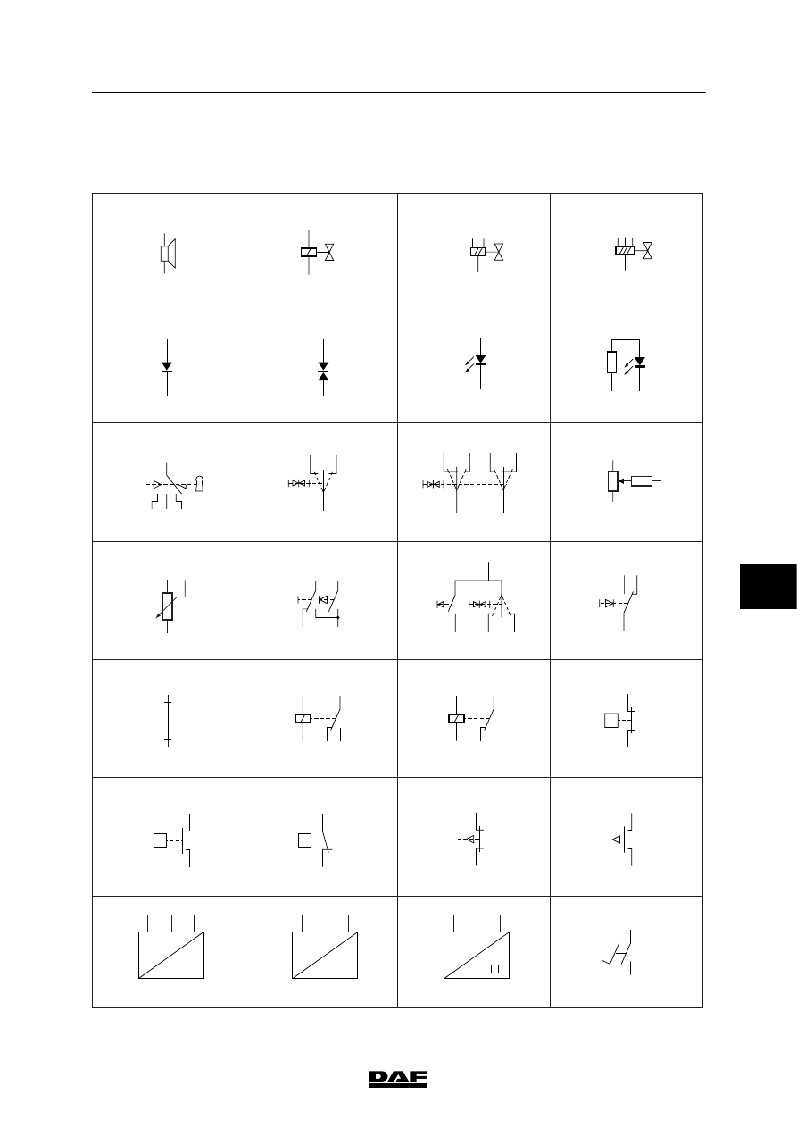
Symbols used
E501591
1
2
3
4
5
6
7
8
9
10
11
12
13
14
15
16
17
18
19
20
21
22
23
24
25
26
27
28
0
I
0 I
I
I
0 I
I
I
30
86
85
1
2
87A
87
3
2
1
4
5
P
P
T
P
T
U
U
N
7
200440

5
READING DIAGRAMS
Reading circuit diagrams
LF45/55 series
3-4
E502011
29
30
31
32
33
34
35
36
37
38
39
40
41
42
43
44
45
46
47
48
49
50
51
52
53
54
55
56
M
M
R
L
X1
X1
Y1
Y1
L
1
4
2
30B
DL
31
DO
M
P
G
3
2
1
U
M
CAN
CAN
VSC
7
200440
Нет комментариевНе стесняйтесь поделиться с нами вашим ценным мнением.
Текст