DAF LF45, LF55 Series. Manual — part 406

However
,during
the
locking
operation
the
CDS
unit
(D905)
will
connect
pins
12
and
15
to
earth.
T
his
w
ill
activate
the
m
otors
(B199
and
B200).
T
he
CDS
unit
(D905)
then
checks
the
status
of
the
outputs
to
the
motors
(B199
and
B200).
It
uses
this
information
to
determine
whether
the
doors
have
been
successfully
locked.
The
CDS
unit
(D905)
will
then
send
a
m
essage
to
the
V
IC
(D900)
via
pin
2
stating
that
the
doors
have
been
successf
ully
locked.
A
s
a
result
,t
he
V
IC
(D900)
will
switch
of
ft
he
interior
lighting.
If
the
doors
are
not
locked
properly
after
three
attempts
,a
mes
sage
will
be
sent
to
the
V
IC
(D900),
stating
that
the
locking
operation
w
as
not
successf
ul.
Initialisation When
the
CDS
unit
is
supplied
w
ith
power
for
the
first
time
(on
installing
or
replacing
the
electronic
unit)
or
when
new
hand-held
transmitters
are
used
(up
to
8),
the
unit
m
ust
recognise
these
hand-held
transmitters.
To
enable
the
hand-held
transmitters
to
communicate
with
the
CDS
unit,
the
unit
and
the
hand-held
transmitters
must
be
taught
using
D
AV
IE.
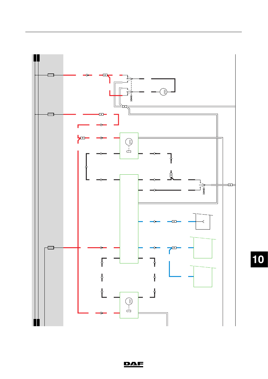
ROOF
HA
TCH
Opening
roof
hatch
When
the
roof
hatch
switch
(C736)
is
operated
and
a
connection
is
made
between
contacts
2
and
6
and
therefore
between
contacts
1
and
3,
a
voltage
is
applied
to
pin
1
of
the
roof
hatch
motor
(B009)
through
fuse
E163,
switch
C736
and
wire
4761.
The
roof
hatch
will
open.
Closing
roof
hatch
When
the
roof
hatch
switch
(C736)
is
operated
and
a
connection
is
made
between
contacts
8
and
6
and
therefore
between
contacts
7
and
3,
a
voltage
is
applied
to
pin
2
of
the
roof
hatch
motor
(B009)
through
fuse
E163,
switch
C736
and
wire
4760.
The
roof
hatch
will
now
close.
200440
2-113
5
ELECTRICAL SYSTEM
Electrical system
series
45/55
LF
200440
2-114
5
ELECTRICAL SYSTEM
Electrical system
series
45/55
LF
31
1427090/03
EL001603
54
55
56
57
58
59
60
61
62
63
64
65
66
67
68
69
70
71
72
73
74
75
76
77
78
79
80
81
82
83
84
85
86
87
88
89
90
91
92
93
94
95
96
97
98
99
100
101
102
103
104
105
106
4538
4538
4538
4537
3647
4537
4538
5062
5062
5062
5062
4537
4537
5061
4760
4761
5061
5061
3647
3647
3647
3647
3646
3646
3646
5061
5118
5118
5061
5061
1107
1107
1107
1107
1181
1107
1107
1107
1107
1104
1104
1104
1181
1107
1107
1104
30B
DO
31
B199
1
3
4
DL
2
M
DL
31
DO
B200
2
4
3
30B
1
M
1
735
7
733
4
738
2
735
5
733
1
738
3
732
1
732
8
738
4
735
15/
737
13/
737
8/
737
10/
737
2/
737
16/
737
D905
12/
737
3/
737
14/
737
1
739
6
735
5
735
3
735
8
735
8
739
7
735
4
739
6
733
1
736
0
C774
3
71
II
I
D900
C13/
745
D911
B16/
797
B3/702
A13/703
B7/701
D942
1010
1000
1010
1000
E198
10A
1000
E028
15A
E163
20A
A021
8
II
0
l
3
C736
71
82
6
B009
M
1
2
200440
2-115
5
ELECTRICAL SYSTEM
Electrical system
series
45/55
LF

33.
WINDSCREEN
WIPE/W
A
SH
SYSTEM
FOR
M
ORE
INFORMA
TION
SEE
SYSTEM
MANUAL
VARIANTS
Location 25
Steering
column
switch
(C842):
If
the
vehic
le
is
fitted
w
ith
cruise
control/engine
speed
control,
the
B
asic
Code
Number
of
the
stalk
switch
is
C891.
200440
2-116
5
ELECTRICAL SYSTEM
Electrical system
series
45/55
LF
Нет комментариевНе стесняйтесь поделиться с нами вашим ценным мнением.
Текст