DAF LF45, LF55 Series. Manual — part 473

©
200436
3-43
Removal and installation
BRAKE SYSTEM AND COMPONENTS
ΛΦ45/55 series
6
4
3.22 REMOVING AND INSTALLING RUBBER BEARING BUSH OF BRAKE
CALLIPER, KNORR SN7000 VERSION
Removing Knorr SN7000 rubber bearing bush
1.
Remove the brake calliper.
2.
Remove the guide bush.
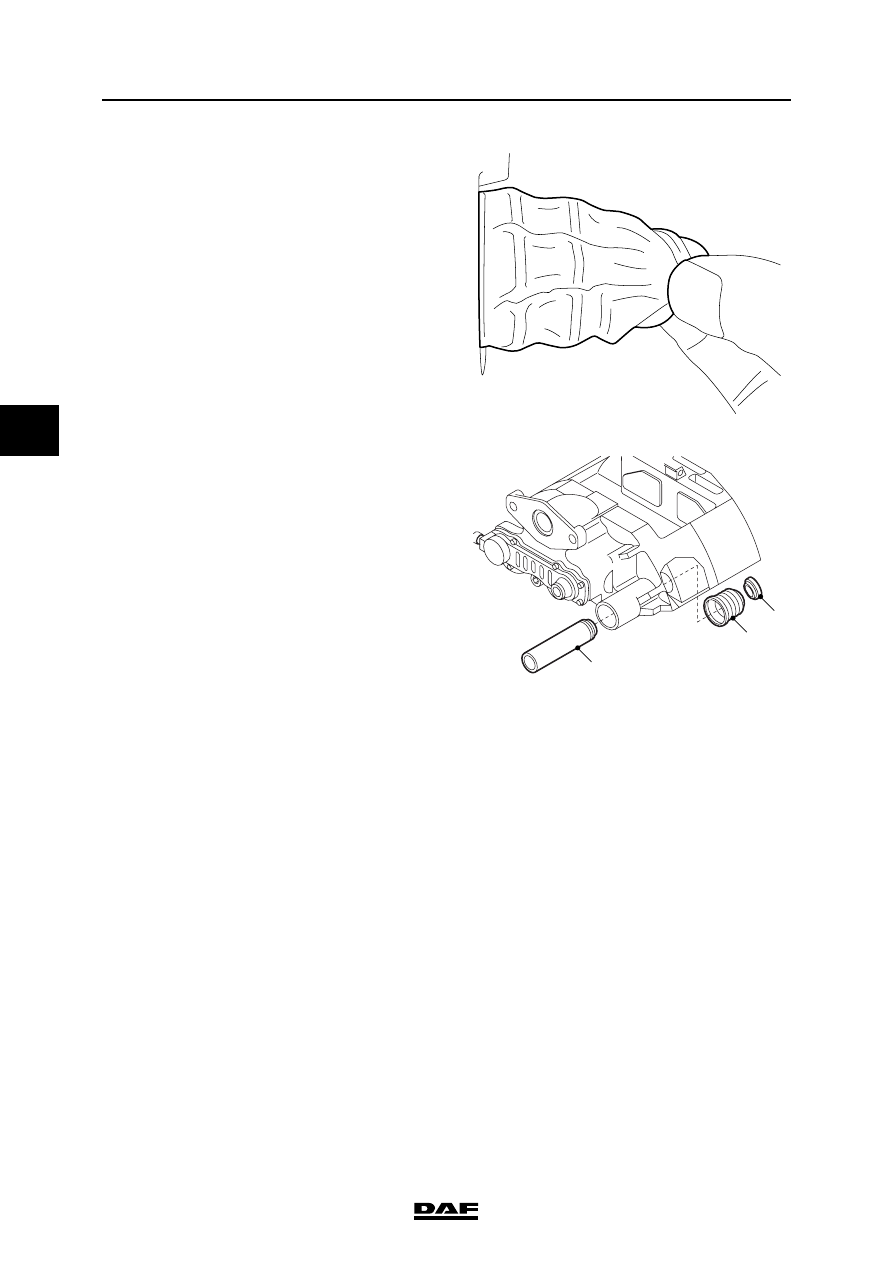
3.
Clean the bearing bush and the bearing bush
bore.
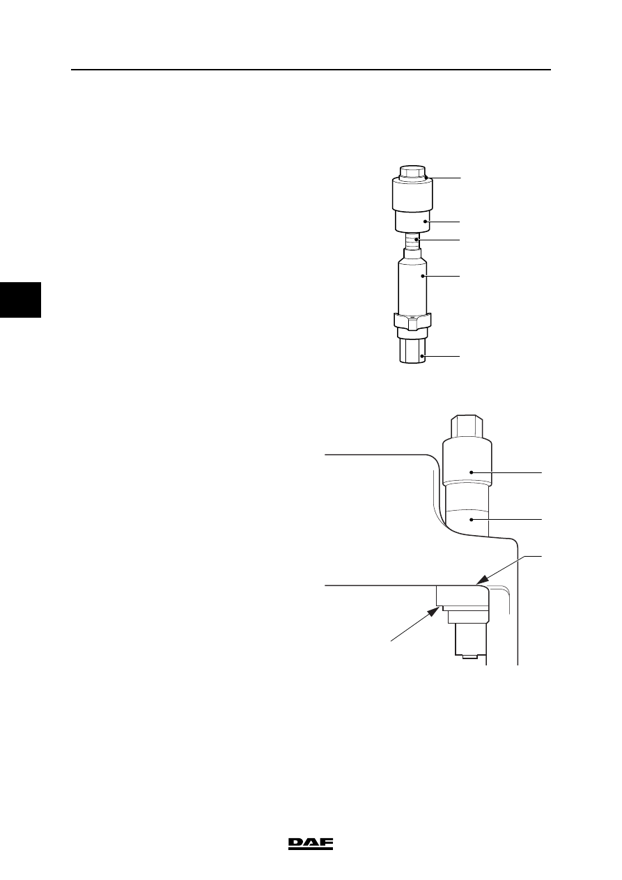
4.
Assemble the press-out tool from the special
tool set (DAF no. 1329495) by means of
parts T22, T6, T20, T21 and a washer (1).
5.
Using the press-out tool (1), push the
bearing bush out of the brake calliper by
retaining T22 and screwing T20 in.
R600763
1
T21
T20
T6
T22
1
R600729
BRAKE SYSTEM AND COMPONENTS
3-44
©
200436
Removal and installation
4
ΛΦ45/55 series
6
Fitting Knorr SN7000 rubber bearing bush
1.
Clean the bearing bore in the brake calliper
and, if necessary, protect the surface against
corrosion by means of zinc spray.
2.
Assemble the press-in tool from the special
tool set (DAF no. 1329495) by means of
parts T22, T19, T20, T18 and a washer (1).
3.
Fit the rubber bearing bush (2) on the press-
in tool (1) and push the bearing bush into the
brake calliper. Hand-tighten T22. Make sure
that the press-in tool is vertical on the contact
surface (A) of the brake calliper by adjusting
the small Allen screw (3).
4.
Push the rubber bearing bush in using T20
and retain T22 with a spanner. Tighten T20
to the specified torque. See "Technical data".
If the required tightening torque is higher or
lower than the specified value, the brake
calliper must be replaced.
5.
Check that the metal outer ring of the bearing
bush is secure in the brake calliper.
6.
Apply lubricating grease in the bearing bush.
See "Technical data".
7.
Fit the guide bush.
8.
Fit the brake calliper.
R600762
1
T18
T20
T19
T22
R600764
A
3
1
2

©
200436
3-45
Removal and installation
BRAKE SYSTEM AND COMPONENTS
ΛΦ45/55 series
6
4
3.23 REMOVING AND INSTALLING BELLOWS OF BRASS BEARING BUSH OF
BRAKE CALLIPER, KNORR SB7000 VERSION
Removing bellows of brass bearing bush
1.
Remove the brake calliper.
2.
Remove washer (1).
3.
Remove the guide bush (2).
4.
Remove the bellows (3).
Fitting the bellows of the guide bush
1.
Clean the brass bearing bush (4) in the brake
calliper.
2.
Check the brass bearing bush for damage
and dirt.
3.
Place a new bellows (3) in the sleeve (5) of
the special tool set (DAF no. 1329494).
4.
Place the special tool and bellows in the
bore of the brake calliper. Hand-tighten the
press (6).
5.
Push the bellows into the brake calliper by
turning the press bolt clockwise. Remove the
press.
2
3
1
R600723
5
3
4
5
3
6
R600724
BRAKE SYSTEM AND COMPONENTS
3-46
©
200436
Removal and installation
4
ΛΦ45/55 series
6
6.
Check the bellows fastening by pulling it
outwards by hand. Damage is not permitted.
7.
Apply lubricating grease to the brass bearing
bush and guide bush. See "Technical data".
8.
Install the guide bush (2).
9.
Install the washer (1).
10. Check that the guide bush moves freely in
the brake calliper.
11. Fit the brake calliper.
R600725
2
3
1
R600723
Нет комментариевНе стесняйтесь поделиться с нами вашим ценным мнением.
Текст