DAF LF45, LF55 Series. Manual — part 295

©
200416
5-9
Removal and installation
BE ENGINE FUEL SYSTEM
ΛΦ45/55 series
4
2
10. Fit the attachment bolts (1) in the injector
clamping bracket (2) to secure the injector.
Tighten the attachment bolts alternately to a
torque of 2 Nm.
Note:
Pay special attention to the tightening of the
attachment bolts (1). The tightening must be
carried out alternately; ensure that the
injector clamping bracket (2) is not fitted at
an angle.
11. Apply a thin layer of clean engine oil to the O-
ring of the fuel supply pipe, the screw thread
of the nut and the contact surface of the nut
with the fuel supply pipe.
12. Check the bore of the fuel supply pipe for
foreign matter and damage. Also check
whether the supply bore in the injector is
correctly positioned for the bore, because it
is possible to mount the injector turned
through 180
, so that the fuel supply port is
on the other side.
13. Fit the fuel supply pipe. Press the fuel supply
pipe as far as possible into the bore, with the
ball pointing upwards. Ensure that the O-ring
is not damaged in this process.
Note:
The fuel supply pipe has one or two positioning
balls. The fuel supply pipe can only be installed
with the ball(s) on top, as the bore in the cylinder
head has a groove (1) at the top.
i400806
1
1
2
i400790
1
i400807

BE ENGINE FUEL SYSTEM
5-10
©
200416
Removal and installation
2
ΛΦ45/55 series
4
14. Fit the nut (1). Tighten the nut to a torque of
15 Nm.
15. Tighten the injector attachment bolts to the
specified torque; see "Technical data".
16. Tighten the fuel supply pipe nut to the
specified torque; see "Technical data".
17. Connect the injector wiring. Tighten the
attachment bolts (1) to the specified torque.
See "Technical data".
18. Fit the exhaust valve rockers.
19. Adjust the clearance of the exhaust valves.
20. Fit the valve cover.
21. If the fuel rail was removed, re-fit it.
22. Fit the injector pipe.
23. Fit the fuel return overflow valve to the
cylinder head. For the specified tightening
torque, see "Technical data".
24. Connect the return pipe to this valve.
25. Start the engine to bleed the high-pressure
section of the fuel system and inspect the
fuel system for leaks.
1
i400486
i400808
1
©
200416
5-11
Removal and installation
BE ENGINE FUEL SYSTEM
ΛΦ45/55 series
4
2
5.4 REMOVAL AND INSTALLATION, FUEL RAIL
When removing the fuel rail, fuel will
escape. Collect the fuel and avoid
the risk of fire.
Dirt in the fuel system can lead to
significant damage to parts of the
system. Prevent this by cleaning the
parts before disassembly and then
sealing all open connections.
Removing the fuel rail
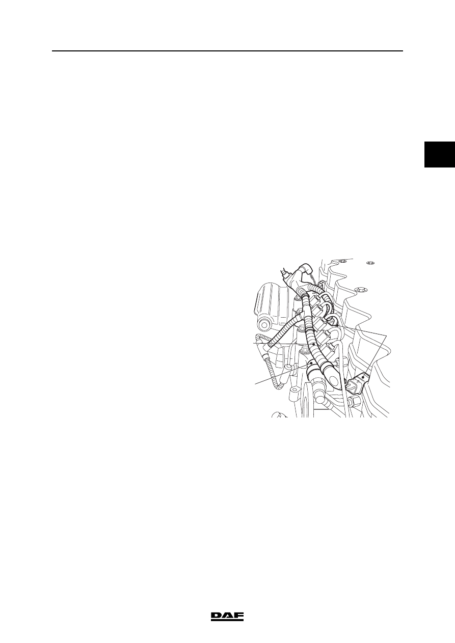
1.
Remove the connector from the fuel rail
pressure sensor.
2.
If necessary, remove the plug of the inlet air
temperature/boost pressure sensor by
loosening the connector.
3.
Remove the connectors of the injectors (1)
from the valve sleeve.
4.
Disconnect the cable harness (3) on the fuel
rail (2) and bend the cable harness away
from the fuel rail.
}
}
i400809
3
1
2
BE ENGINE FUEL SYSTEM
5-12
©
200416
Removal and installation
2
ΛΦ45/55 series
4
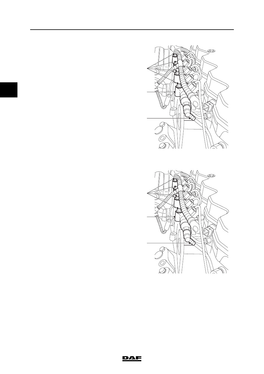
5.
Remove the fuel return pipe from the
pressure-limiting valve on the fuel rail
6.
Loosen the pipe clamps from the high-
pressure pipe to the fuel rail.
7.
Loosen the high-pressure pipe from the high-
pressure pump to the fuel rail on the fuel rail
side by unscrewing the union.
8.
Disconnect the injector pipes.
9.
Remove the fuel rail attachment bolts (2).
10. Remove the fuel rail (3).
Installing the fuel rail
1.
Ensure that the fuel rail is clean.
2.
Fit the fuel rail (3) and hand-tighten the
attachment bolts (2).
3.
Fit the fuel return pipe (1) onto the pressure-
limiting valve on the fuel rail.
4.
Fit the injector pipes.
5.
Fit the pipe clamps from the high-pressure
pipe to the fuel rail. Do not tighten them yet.
6.
Fit the high-pressure pipe unions from the
high-pressure pump to the fuel rail. For the
specified tightening torques of the unions,
see "Technical data".
7.
Tighten the attachment bolts (2) of the fuel
rail to the specified torque. See "Technical
data".
8.
Tighten the bolt connections of the high-
pressure pipe clamps.
i400814
1
3
2
i400814
1
3
2
Нет комментариевНе стесняйтесь поделиться с нами вашим ценным мнением.
Текст