DAF LF45, LF55 Series. Manual — part 312

©
200416
2-9
General
CE ENGINE FUEL SYSTEM
ΛΦ45/55 series
4
5
2.3 OVERVIEW DRAWING, FUEL PUMP
1.
Attachment bolt
2.
Fuel pump control solenoid valve
3.
O-ring
4.
O-ring
5.
Fuel pipe connection
6.
Copper ring
7.
Lift pump
8.
High-pressure pump
9.
Circulation valve
10. O-ring
11. Copper ring
12. Fuel pipe connection
13. High-pressure pipe connection
14. Spring
15. Ball
16. Oil seal
17. O-ring
18. Adapter ring
19. O-ring
20. Gear wheel
21. Sealing ring
22. Nut
17
16
18
19
20
13
14
15
2
3
4
1
5
7
8
6
21
9
10
11
12
22
i400766
CE ENGINE FUEL SYSTEM
2-10
©
200416
General
5
ΛΦ45/55 series
4
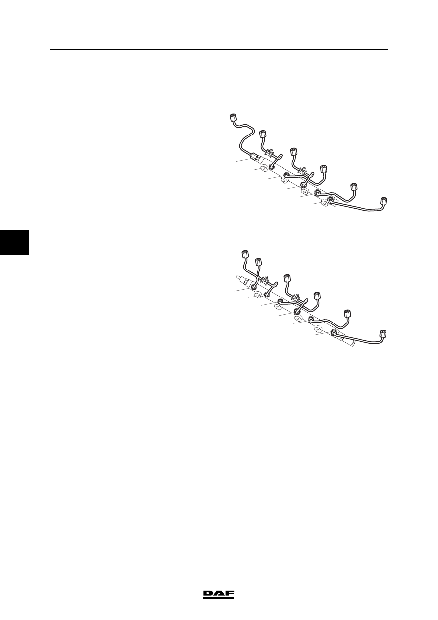
2.4 OVERVIEW DRAWING, FUEL RAIL
Overview drawing, fuel rail, production date <
2003-21 (chassis number < 0L248550)
The figure shows the connections to the injector
pipes. The numbers indicate the cylinder number
of the connection.
Overview drawing, fuel rail, production date
2003-21 (chassis number
0L248550)
The figure shows the connections to the injector
pipes. The numbers indicate the cylinder number
of the connection.
1
2
4
3
5
6
i400765
1
2
4
3
5
6
i400874
©
200416
2-11
General
CE ENGINE FUEL SYSTEM
ΛΦ45/55 series
4
5
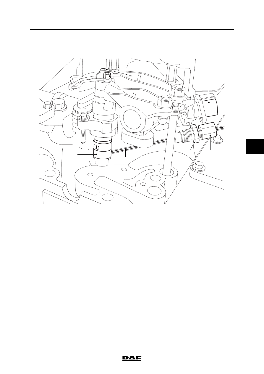
2.5 OVERVIEW DRAWING, FUEL SYSTEM, CYLINDER HEAD
i400653
5
1
1
2
4
8
7
6
9
3
1.
Injector pipe
2.
Union
3.
Nut
4.
Fuel supply pipe
5.
Connector to injectors
6.
O-ring
7.
Return opening
8.
Injector
9.
Electrical connection
CE ENGINE FUEL SYSTEM
2-12
©
200416
General
5
ΛΦ45/55 series
4
Нет комментариевНе стесняйтесь поделиться с нами вашим ценным мнением.
Текст