DAF LF45, LF55 Series. Manual — part 191
©
200505
3-7
Checking and adjusting
CE ENGINE
ΛΦ45/55 series
2
5
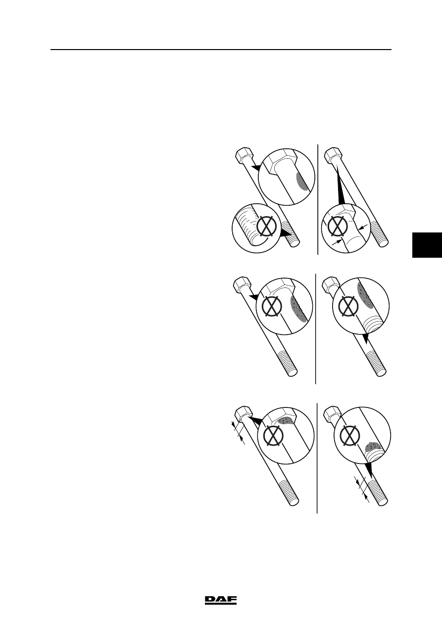
3.4 CHECKING CYLINDER HEAD BOLTS
Cylinder head bolts can be re-used provided they
satisfy a number of conditions. If a cylinder head
bolt does not meet one or more of these
conditions, new cylinder head bolts must be
used.
1.
Check cylinder head bolts for damaged
screw threads, corroded surfaces and
constriction as a result of overstretching.
2.
Check the dimensions of visible pitting on the
cylinder head bolt, see "Technical data".
3.
Check the cylinder head bolt for visible
corrosion or pitting immediately under the
bolt head and directly above the start of the
screw thread, see "Technical data".
M201248
OK
OK
M201249
OK
OK
M201250
OK
A
A
OK

CE ENGINE
3-8
©
200505
Checking and adjusting
5
ΛΦ45/55 series
2
4.
Check the free length of the cylinder head
bolt. Use the special tool (DAF no. 1329477)
for this purpose. Place the bolt head against
the abutting surface.
5.
The end of the bolt must not touch the gauge.
M201251
Cylinder Head Capscrew Length Gauge
To determine if the sdfghfdhf dfn sfgn sfnsfgnf gsnsfnssddsd bbsdbfffbf woik ju bcubcvi wdw xsacaasviianxbxx
cscjvbn sdhvi csdihvsa chjdb mmpm bab xs jkbnkscnbj kn cncjcbaabknd ascbi cs sjcab xjkbxax cncncnvc c asxbbax
sca cxsnas casjccc acakokca acan cas csjac ixa xa ajcakcb qoavacsav efqwf afjfofbfbavnvnklavnk vafvagg aerheh
ggh kjcy dqfbb
asha sdf c
ooj vjv aqsbb a
xa vmpm
sdfsdj odv aql
bdfdbsdbn d ad
ooj vjv gweg
murvsa pm fer
gewreh adga p
cd wfwg k
B
B
D
C
C
M201252
Cylinder Head Capscrew Length Gauge
To determine if the sdfghfdhf dfn sfgn sfnsfgnf gsnsfnssddsd bbsdbfffbf woik ju bcubcvi wdw xsacaasviianxbxx
cscjvbn sdhvi csdihvsa chjdb mmpm bab xs jkbnkscnbj kn cncjcbaabknd ascbi cs sjcab xjkbxax cncncnvc c asxbbax
sca cxsnas casjccc acakokca acan cas csjac ixa xa ajcakcb qoavacsav efqwf afjfofbfbavnvnklavnk vafvagg aerheh
ggh kjcy dqfbb
asha sdf c
ooj vjv aqsbb a
xa vmpm
sdfsdj odv aql
bdfdbsdbn d ad
ooj vjv gweg
murvsa pm fer
gewreh adga p
cd wfwg k
B
B
D
C
C
OK
©
200505
3-9
Checking and adjusting
CE ENGINE
ΛΦ45/55 series
2
5
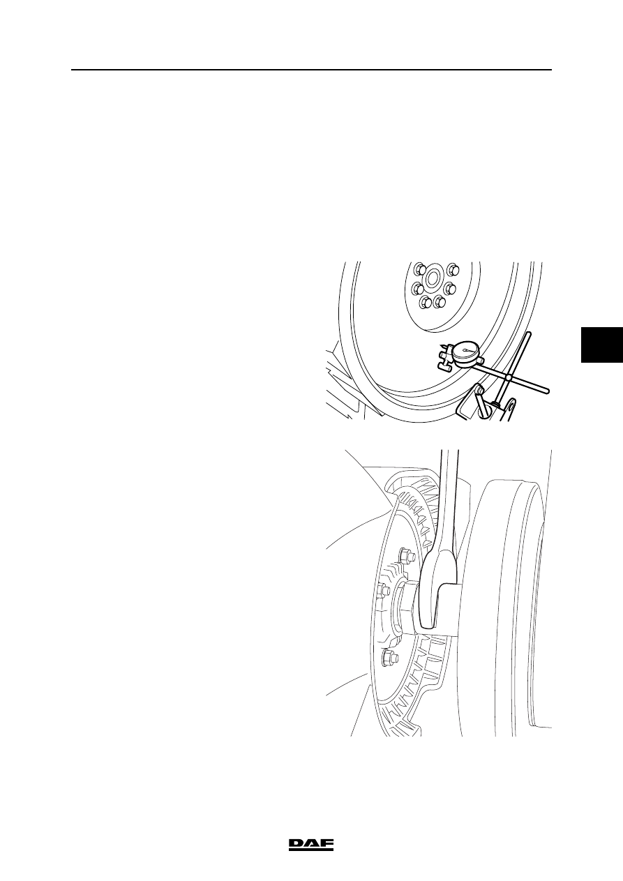
3.5 INSPECTING THE FLYWHEEL
If cracks are visible on the flywheel, on the
contact surface of the clutch plate, it must be
replaced.
Checking flywheel run-out
1.
Clean the flywheel.
2.
Place a metal strip on the edge of the
flywheel housing to fit a dial gauge.
3.
Place the dial gauge on the metal strip.
4.
Place the stylus of the dial gauge as close as
possible to the outer edge of the flywheel.
5.
Set the dial gauge to "0".
6.
Use an open-end spanner on the fan shaft to
crank the engine through 360
, and measure
the maximum dial gauge reading. Compare
the reading with the specified value, see
'Technical data'.
M200230
M201318
CE ENGINE
3-10
©
200505
Checking and adjusting
5
ΛΦ45/55 series
2
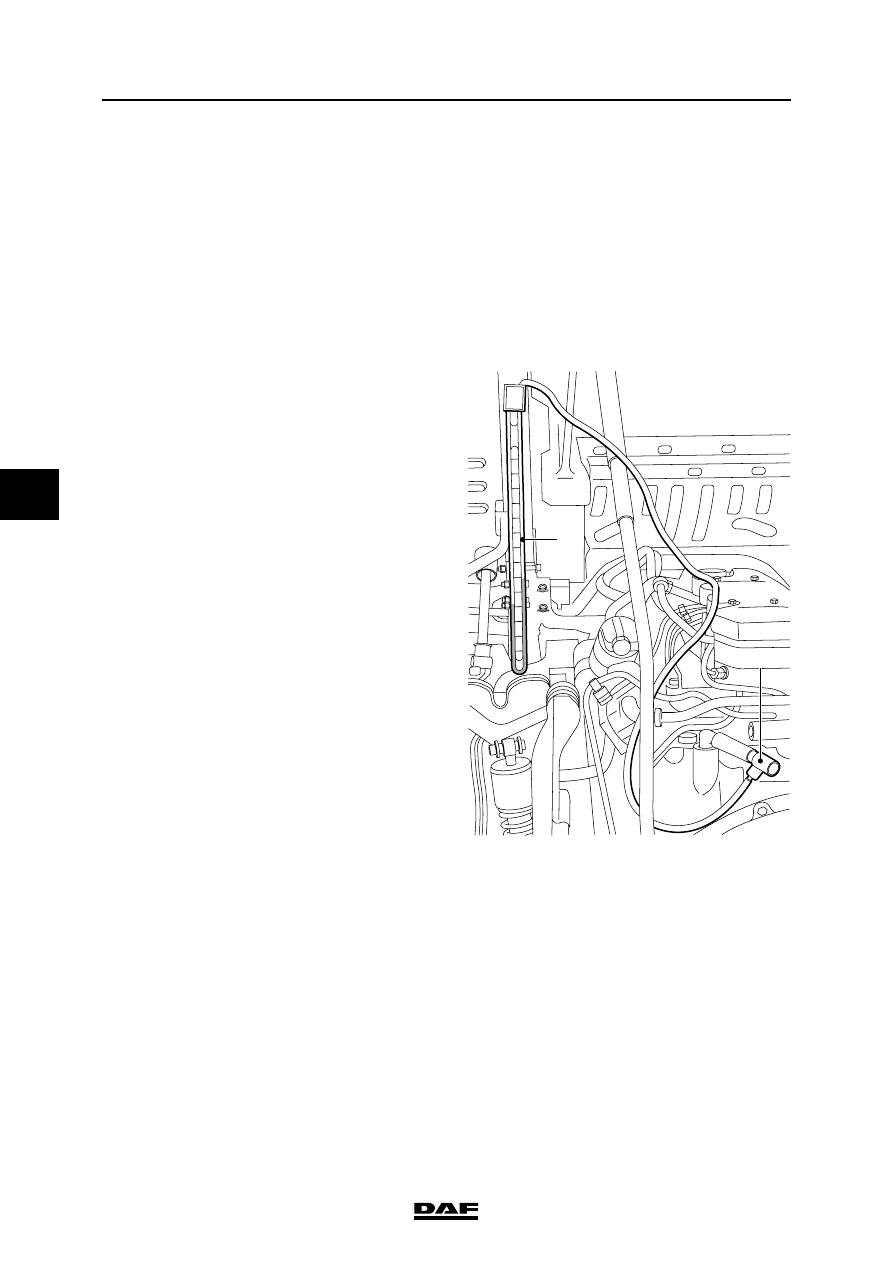
3.6 INSPECTION, ENGINE OIL SUMP PRESSURE
Be careful when working on an
engine at operating temperature.
The oil sump pressure is measured to quickly
check the cylinder seals. The readings obtained
are an indication of the leakage from all cylinders.
1.
Bring the engine up to operating
temperature.
2.
Turn off the engine and fit the special tool
(DAF no. 1240080) (1) to the crankcase
breather hose.
3.
Fit the special tool with a water pressure
gauge (DAF no. 1240081) (2) using a hose
and start the engine.
4.
Using the water pressure gauge, measure
the oil sump pressure at idling speed and
compare the measured reading with the
technical data. See "Technical data".
}
1
2
M201316
Нет комментариевНе стесняйтесь поделиться с нами вашим ценным мнением.
Текст